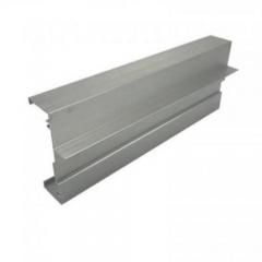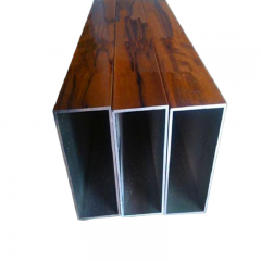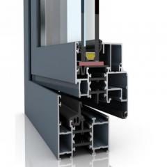
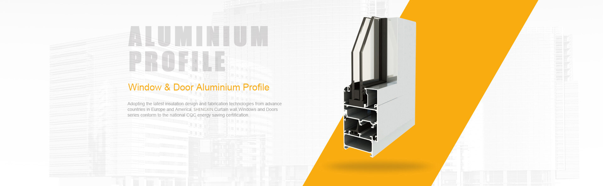
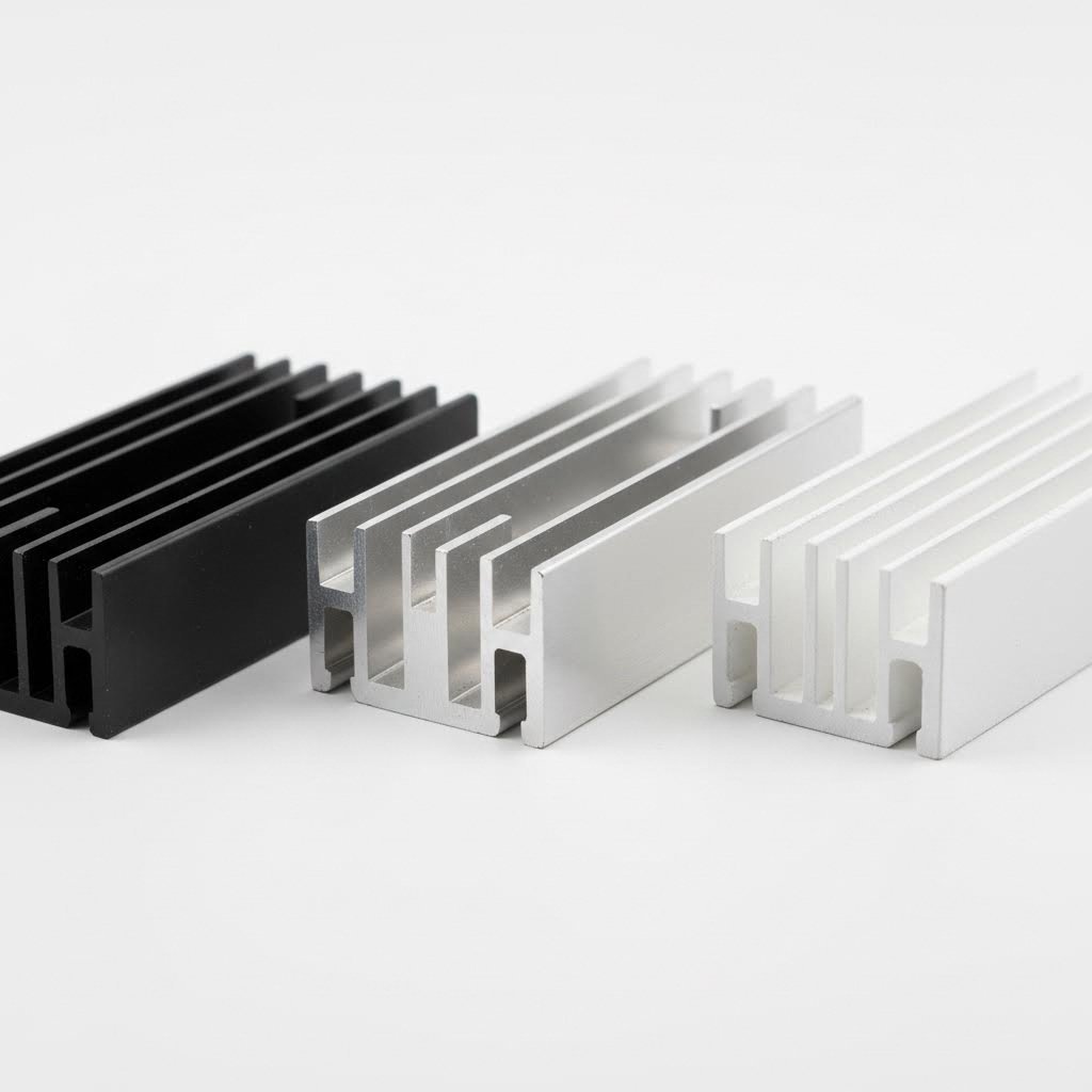
Ever wondered how the cooling fins inside your laptop or LED light fixture get their precise, intricate shapes? The answer lies in a manufacturing process called heat sink aluminum extrusion—a method that has quietly revolutionized thermal management across nearly every industry you can imagine.
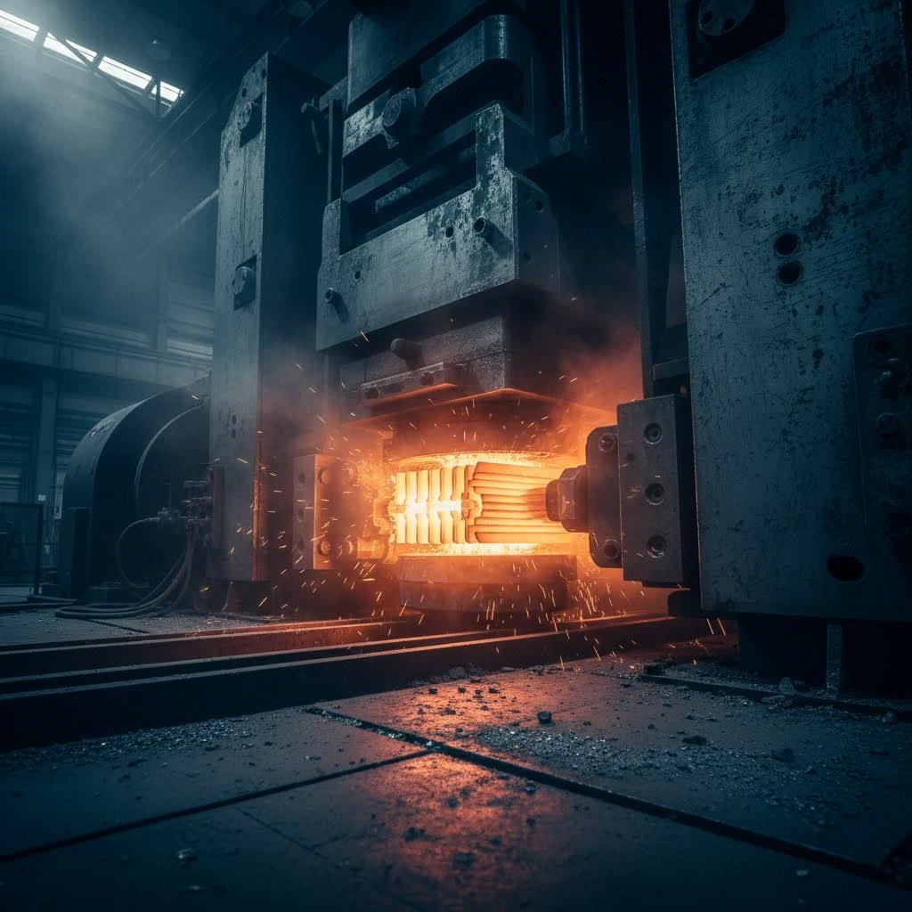
At its core, this process involves forcing heated aluminum billets through precision-engineered dies under immense pressure. Think of it like squeezing toothpaste through a shaped nozzle, except the "toothpaste" is softened aluminum heated to approximately 900°F (482°C), and the "nozzle" is a custom-designed steel die. The result? Long, continuous profiles featuring complex fin geometries that would be nearly impossible to achieve through other manufacturing methods.
This extruded heat sink technology has become the dominant choice for thermal management components in electronics, LED lighting, power electronics, electric vehicles, and industrial applications. But why has aluminum extrusion specifically claimed this position over alternatives like die casting or CNC machining?
The popularity of aluminum heat sink manufacturing through extrusion comes down to a perfect storm of material properties and process advantages. Consider what makes this combination so compelling:
According to the Aluminum Extruders Council, aluminum's thermal conductivity makes it ideal for dissipating heat from electric motors, electronic devices, LED lights, and even battery packs for electric vehicles.
Understanding why heatsink aluminium profiles work so effectively requires a quick look at heat transfer principles. When electronic components generate heat, that thermal energy needs somewhere to go. An extruded heat sink accomplishes this through three mechanisms: conduction (moving heat through the aluminum base), convection (transferring heat to surrounding air via the fins), and radiation (emitting thermal energy from surfaces).
While aluminum's thermal conductivity is lower than copper's 400 W/(m·K), its superior extrudability, lighter weight, and significantly lower cost make it the optimal choice for the vast majority of thermal management applications.
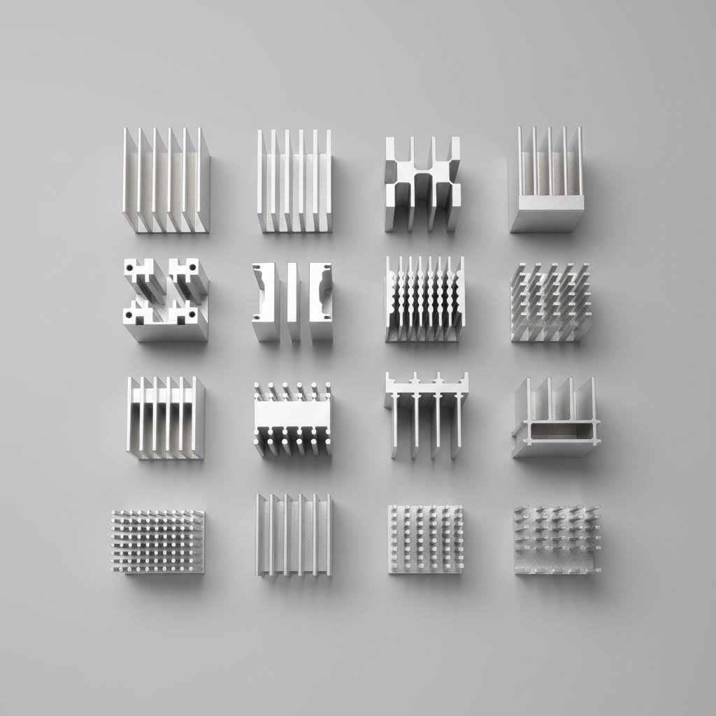
The heat sink extrusion process excels at creating thin, tall fins that dramatically increase surface area without adding excessive weight. This geometric flexibility is something copper simply cannot match cost-effectively—its softness and weight make extruding complex shapes far more difficult and expensive.
Throughout this guide, you'll discover an engineering-first approach to understanding aluminum heat sink technology. We'll explore the manufacturing process in detail, compare the two most popular aluminum alloys (6061 and 6063), examine design principles that maximize thermal performance, and provide practical guidance for selecting the right profile for your application. By the time you finish reading, you'll have the foundational knowledge needed to make confident, informed decisions about your thermal management needs.
Now that you understand why aluminum extrusion dominates the thermal management industry, let's walk through exactly how those intricate heatsink extrusion profiles come to life. Surprisingly, few manufacturers explain this process clearly—yet understanding these steps helps you make smarter decisions when specifying extruded heatsinks for your projects.
The journey from raw aluminum to a finished heat sink profile involves carefully controlled temperatures, massive hydraulic pressure, and precision engineering at every stage. Each step directly influences the thermal performance, dimensional accuracy, and surface quality of your final product.
The aluminum extrusion manufacturing process follows a precise sequence that transforms solid aluminum billets into complex extruded heat sink profiles. Here's exactly how it works:
The entire pressing operation happens remarkably fast—often completing in just minutes. However, as noted by extrusion industry research, precision remains paramount throughout. Any variation in temperature, pressure, or speed can result in surface imperfections, dimensional inconsistencies, or internal defects that compromise thermal performance.
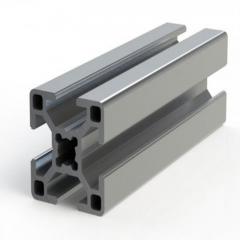
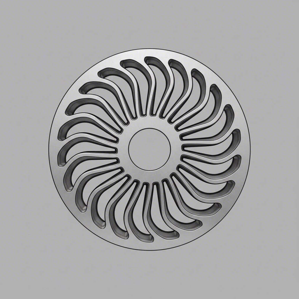
If the extrusion press is the heart of the process, the die is its brain. This precision-engineered tool—typically machined from high-strength H13 tool steel—determines everything about your heat sink's geometry: fin height, fin thickness, fin spacing, and base dimensions.
When you're specifying extruded heat sink profiles, understanding die capabilities helps you optimize your design:
The extrusion press tonnage plays a crucial role in determining what profiles are achievable. Smaller presses in the 600-1500 ton range handle standard heat sink profiles effectively, while larger presses (3000-5500+ tons) enable bigger cross-sections, more complex geometries, and tighter tolerances for demanding applications. This is why evaluating a manufacturer's press capabilities matters when sourcing custom heatsink profile designs.
Die design also influences the "extrudability" of different aluminum alloys—a factor we'll explore in detail when comparing 6061 and 6063 alloys in the next section. Some alloys flow more easily through complex die geometries, while others require modified designs or slower extrusion speeds to achieve acceptable quality.
Here's the question that trips up even experienced engineers: which aluminum alloy should you specify for your extruded aluminum heatsink? The choice between 6061 and 6063 affects everything from thermal performance to manufacturing cost—yet surprisingly few resources provide a clear, data-driven comparison.
Both alloys belong to the 6000 series, meaning they share magnesium and silicon as primary alloying elements. They're both heat-treatable and corrosion-resistant. But dig into the details, and you'll discover meaningful differences that influence which aluminum heat sink material works best for your specific application.
Let's break down what actually matters when selecting between these two popular alloys.
If you've ever handled an aluminum heat sink from LED lighting, architectural fixtures, or consumer electronics, chances are excellent it was made from 6063 aluminum. There's a good reason this alloy dominates the extruded aluminum heat sink material market.
According to material property data from MakeItFrom.com, 6063-T6 aluminum delivers thermal conductivity of approximately 200 W/(m·K)—roughly 18% higher than its 6061 counterpart. For thermal management applications, this difference translates directly into improved heat dissipation performance.
But thermal conductivity is just the beginning of 6063's advantages:
When does 6063 make the most sense? Consider it your default choice for standard aluminum heatsink applications where thermal performance takes priority over mechanical strength. LED lighting housings, telecommunications equipment enclosures, and consumer electronics cooling solutions typically specify 6063 because these applications need efficient heat transfer combined with attractive appearance—not structural load-bearing capability.
Now imagine a different scenario: your heat sink big enough to cool industrial power electronics will also serve as a structural mounting plate. Or perhaps it needs to withstand significant mechanical stress, vibration, or impact loading. This is where 6061 aluminum earns its place.
Originally developed in 1935 for aircraft applications, 6061 aluminum prioritizes mechanical strength over extrudability. Reference data shows 6061-T6 delivers ultimate tensile strength of 310 MPa compared to 6063-T6's 240 MPa—a 29% improvement in load-bearing capability.
The trade-offs for this added strength are worth understanding:
Engineers typically specify 6061 extruded aluminum heatsink profiles when the component must handle structural loads, resist fatigue from vibration, or serve dual thermal-mechanical functions. Think industrial motor controllers, power inverters in demanding environments, or aerospace applications where strength-to-weight ratio matters alongside thermal management.
To help you make an informed decision, here's a comprehensive comparison of both alloys based on verified material property data:
| Property | 6061-T6 Aluminum | 6063-T6 Aluminum | Which Is Better For Heat Sinks? |
|---|---|---|---|
| Thermal Conductivity | 170 W/(m·K) | 200 W/(m·K) | 6063 (18% higher) |
| Ultimate Tensile Strength | 310 MPa | 240 MPa | 6061 (29% stronger) |
| Yield Strength | 270 MPa | 210 MPa | 6061 (29% higher) |
| Extrudability Rating | Good | Excellent | 6063 (easier complex profiles) |
| Surface Finish Quality | Good | Excellent | 6063 (smoother as-extruded) |
| Density | 2.70 g/cm³ | 2.69 g/cm³ | Essentially equal |
| Corrosion Resistance | Excellent | Excellent | Both perform well |
| Relative Material Cost | Similar | Similar | 6063 often lower total cost |
| Typical Applications | Structural/high-stress thermal components | Standard thermal management | Application-dependent |
Notice that while base material costs are comparable, 6063's superior extrudability often translates to lower total manufacturing costs—especially for complex profiles with high fin counts or thin geometries.
So how do you decide? Consider these guiding principles:
Choose 6063 when:
Choose 6061 when:
For most standard thermal management applications—LED cooling, electronics enclosures, telecommunications equipment—6063 remains the industry-standard choice. Its combination of superior thermal conductivity, excellent extrudability, and attractive surface finish simply makes it the most practical aluminum heat sink material for the majority of projects.
However, when your application demands both thermal management and mechanical performance, don't hesitate to specify 6061. The slight reduction in thermal efficiency is often acceptable when structural integrity is non-negotiable.
Understanding the fundamental differences between these alloys is just the beginning. To maximize your heat sink's effectiveness, you'll also need to optimize the physical design—starting with fin geometry and spacing, which we'll explore next.
You've selected the right aluminum alloy for your application. Now comes the question that truly separates adequate thermal solutions from exceptional ones: how do you optimize the physical design of your heat sink fins to maximize heat dissipation?
Here's the reality—choosing between 6061 and 6063 aluminum might affect your thermal performance by 15-18%. But get your fin geometry wrong, and you could easily sacrifice 30-50% of your heat sink's cooling potential. The geometry of your finned heatsink determines how effectively heat transfers from the base into the surrounding air, regardless of which alloy you've specified.
Let's explore the design principles that thermal engineers use to optimize aluminum heat sink fins for real-world performance.
When you look at a finned heat sink, you're seeing a carefully balanced compromise between competing requirements. More fins mean more surface area for heat transfer—but pack them too tightly, and you'll restrict the airflow that carries heat away. Taller fins extend your cooling reach—but make them too tall without adequate thickness, and they won't conduct heat efficiently to their tips.
Understanding these trade-offs starts with knowing your key design parameters:
The relationship between these parameters determines your heat sink's aspect ratio—basically, the comparison of fin height to the gap between fins. According to thermal engineering research from Advanced Thermal Solutions, typical heat sinks feature aspect ratios between 3:1 and 5:1, while high-performance designs can reach 8:1 to 16:1 or greater.
Why does this matter? A high aspect ratio heat sink packs more heat-dissipating surface area into the same footprint. You're essentially getting more cooling capacity without expanding the length or width of your thermal solution. However, there's a catch—those tightly spaced, tall fins demand adequate airflow to function properly.
Here's where many engineers make costly mistakes: designing heat sink fins without considering the cooling environment. The optimal fin geometry for passive cooling looks dramatically different from what works best with active fan cooling.
Natural convection applications rely on warm air rising naturally from the heat sink surface. This gentle airflow imposes strict limits on fin design:
Forced convection applications use fans or blowers to actively push air across the fin surfaces. This changes the design equation considerably:
As noted in Celsia's heat sink design fundamentals, convection is "the tail that wags the dog"—it's the primary exit point for heat and ultimately determines how large your heat sink needs to be. Getting the convection strategy wrong undermines everything else in your thermal design.
Imagine pouring water onto the center of a flat surface. The water spreads outward from the point of contact, covering a progressively larger area. Heat spreading in your heat sink base works similarly—thermal energy from your component must spread across the entire base before conducting up into the fins.
If your base is too thin, heat concentrates directly above the component, leaving fins at the edges underutilized. You've paid for surface area that isn't contributing to cooling. Conversely, an excessively thick base adds weight and cost without proportional thermal benefit.
According to industry design guidelines, effective base thickness design follows several principles:
When conduction through the base represents a significant portion of your total thermal resistance, engineers sometimes incorporate heat pipes or vapor chambers into the base design. These two-phase devices can dramatically improve heat spreading—CFD modeling by Celsia showed that adding heat pipes to an aluminum base decreased thermal resistance by almost 50% with only a 2% increase in weight.
So how do you translate these principles into practical design decisions for your aluminum heat sink fins? Consider this framework:
For natural convection applications:
For forced convection applications:
Remember that extrusion manufacturing influences what geometries are achievable. Very thin fins (under 1mm), extremely high aspect ratios, or complex internal features may require specialized tooling or alternative manufacturing methods. Your thermal design must ultimately align with what aluminum extrusion can practically deliver.
With fin geometry optimized for your cooling environment, the next consideration is how extruded heat sinks compare to alternative manufacturing methods—and when each approach makes the most sense for your specific requirements.
You've optimized your fin geometry and selected the ideal aluminum alloy. But here's a question that could significantly impact both your budget and thermal performance: is extrusion actually the right manufacturing method for your heat sink?
The honest answer? It depends. While extruded aluminum heat sink profiles dominate the market for good reason, alternative manufacturing techniques sometimes deliver better results for specific applications. Understanding these trade-offs helps you avoid costly mistakes—like paying premium prices for capabilities you don't need, or settling for inadequate thermal performance when better options exist.
Let's examine how aluminum extrusion heat sink manufacturing stacks up against the competition.
Extrusion has earned its dominant market position through a compelling combination of advantages that most alternatives simply cannot match across the board.
Consider what makes an extruded heatsink particularly attractive:
For medium-to-high volume production—typically 1,000+ units—with moderate fin density requirements, extrusion heat sink manufacturing represents the sweet spot of cost and performance. Most LED lighting, telecommunications, consumer electronics, and general industrial applications fall squarely into this category.
But extrusion isn't always the answer. When does stepping outside this comfort zone make sense?
Each alternative to extrusion addresses specific limitations or unlocks capabilities that standard extrusion cannot achieve. Here's what you need to know about your options:
Skived Heat Sinks
Imagine a specialized blade shaving ultra-thin fins directly from a solid aluminum or copper block in a precise spiral motion. That's skiving—and it produces some of the highest-performance heat sinks available.
According to thermal engineering specialists, skived heat sinks deliver 30-50% more surface area than comparably sized extruded profiles in natural convection applications. Because fins are machined from the same block as the base, there are no assembly joints—meaning excellent thermal continuity throughout the structure.
The trade-off? Those ultra-thin fins (often under 0.5mm) are delicate and prone to bending. Production times run 5-10 minutes per piece, making skiving economical only for volumes under approximately 2,000 units or applications demanding maximum thermal efficiency.
CNC Machined Heat Sinks
When you need just 10, 50, or 100 heat sinks—or when your design features complex three-dimensional geometries impossible to extrude—CNC machining offers unmatched flexibility. Starting from solid aluminum plate or block, machining centers mill, drill, and cut your exact design without any tooling investment.
The per-unit cost remains high regardless of volume, making machining impractical for production quantities. However, for prototyping, low-volume specialty applications, or geometries that simply cannot be extruded, it's often the only viable option.
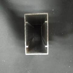
Die Cast Heat Sinks
Die casting injects molten aluminum into precision molds, enabling complex shapes including curved fins, internal channels, and integrated mounting features that extrusion cannot produce. High-volume automotive and consumer electronics applications frequently use die casting for these geometric freedoms.
However, die casting typically uses alloys with lower thermal conductivity than wrought extrusion alloys. The porosity inherent in cast materials can also affect thermal performance. Tooling costs are substantially higher than extrusion dies, making die casting practical only when volumes justify the investment—typically 10,000+ units.
Bonded Fin Assembly
Bonded fin heat sinks attach individual fins to a grooved base plate using thermal epoxy or brazing. This approach enables very tall fins, mixed materials (like aluminum fins on a copper base), and fin densities impossible through extrusion.
The assembly joints introduce some thermal resistance, and per-unit costs remain higher than extrusion due to the multiple operations involved. Bonded fins make sense for specialized high-power applications where performance justifies the cost premium.
Making the right manufacturing choice requires understanding how each method performs across multiple dimensions. This comprehensive comparison highlights the key trade-offs:
| Factor | Extrusion | Skiving | CNC Machining | Die Casting | Bonded Fin |
|---|---|---|---|---|---|
| Tooling Cost | $500-$5,000 | Low (blades, fixtures) | None | $10,000-$50,000+ | $1,000-$3,000 |
| Unit Cost (100 pcs) | High (tooling amortization) | Medium-High | Very High | Very High | High |
| Unit Cost (1,000 pcs) | Medium | Medium | Very High | High | Medium-High |
| Unit Cost (10,000+ pcs) | Low | High | Very High | Low-Medium | Medium |
| Achievable Fin Density | Moderate (1-2mm spacing) | Very High (0.3-0.5mm spacing) | Moderate-High | Low-Moderate | High |
| Thermal Performance | Good | Excellent | Good | Fair-Good | Very Good |
| Lead Time (First Article) | 3-6 weeks | 1-2 weeks | 1-2 weeks | 8-12 weeks | 2-4 weeks |
| Design Flexibility | 2D profiles only | Limited by block size | Nearly unlimited | 3D shapes possible | Tall fins, mixed materials |
| Mechanical Durability | Excellent | Fair (fragile fins) | Excellent | Good | Good |
| Ideal Volume Range | 1,000-1,000,000+ | 100-2,000 | 1-500 | 10,000+ | 500-10,000 |
How do you translate this comparison into a practical decision for your extruded aluminum heat sink project—or determine when alternatives serve you better?
Choose extrusion when:
Consider skiving when:
Select CNC machining when:
Explore die casting when:
Investigate bonded fins when:
It's also worth noting that hybrid approaches are increasingly common for demanding applications. Combining a rugged extruded base with a skived fin block bonded to the surface delivers both mechanical stability and enhanced cooling—a popular solution for EV inverters, telecom modules, and high-reliability electronics.
With your manufacturing method selected, the next step is understanding how surface finishing options can further enhance your heat sink's thermal performance and durability.
You've selected the right alloy, optimized your fin geometry, and chosen extrusion as your manufacturing method. But here's something many engineers overlook: the surface treatment you apply to your heatsink can improve radiation heat transfer by a factor of 15 or more.
Sounds dramatic? Consider this—bare aluminum has an emissivity of just 0.04 to 0.06, meaning it reflects thermal radiation rather than releasing it. Apply an anodized finish, and that emissivity jumps to approximately 0.83 to 0.86. For passive cooling systems with limited airflow, this difference translates directly into measurable temperature reductions.
Let's explore how different surface treatments affect your aluminium heatsink extrusion's performance—and when each option makes sense.
Before diving into specific finishes, understanding why surface treatment matters requires a quick look at heat transfer physics. Your heat sink removes thermal energy through three mechanisms: conduction (through the aluminum itself), convection (transferring heat to moving air), and radiation (emitting thermal energy from surfaces).
In forced-air cooling with powerful fans, convection dominates—surface finish has minimal impact. But in natural convection or low-airflow environments, radiation becomes critically important. According to thermal research from Advanced Thermal Solutions, radiation heat transfer can be as significant as convection in passive cooling applications.
The key variable is emissivity—a material's ability to radiate thermal energy. Surface treatments modify this property dramatically:
This explains why an aluminium heatsink with proper surface treatment can outperform an untreated one by significant margins in passive cooling scenarios—even though the base material properties remain identical.
Anodizing has become the go-to surface treatment for thermal management components, and for good reason. This electrochemical process doesn't simply coat the aluminum—it actually grows a thickened aluminum oxide layer directly from the surface material.
Here's how it works: the aluminum part is submerged in an electrolytic bath (typically sulfuric acid) while electrical current passes through. Oxygen bonds with the aluminum surface, creating a porous oxide layer between 10-25 microns thick for standard applications. This layer is hard, corrosion-resistant, and—crucially—dramatically increases surface emissivity.
The three primary anodizing types serve different needs:
For most heatsink applications, Type II anodizing delivers the optimal balance. The oxide layer is thin enough that thermal conductivity impact remains negligible, while emissivity improvements are substantial.
Here's a question that generates surprising confusion: does black anodizing perform better than clear or colored finishes?
According to thermal engineering research, the answer is nuanced. A clear anodized surface has the same emissive characteristics as a black anodized surface—the oxide layer itself determines emissivity, not the dye color absorbed into its pores.
However, practical testing shows black anodized heatsinks can outperform lighter colors by 3-8% in natural convection scenarios. This difference becomes negligible in forced-air cooling where convection dominates heat transfer.
Bottom line? Choose black anodizing when passive cooling efficiency matters. For forced-air applications, select colors based on aesthetic requirements—thermal differences are minimal.
While anodizing dominates the heatsink market, other surface treatments serve specific applications:
When your heatsink is visible in the final product—think LED lighting fixtures, consumer electronics enclosures, or architectural installations—surface finish decisions involve more than thermal calculations.
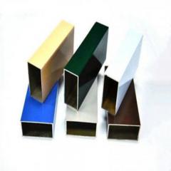
The good news? Anodizing offers both performance and flexibility. Available colors include black, silver, red, blue, gold, and custom shades. Finishes range from matte to satin, with optional anti-fingerprint treatments for high-touch applications.
Consider these guidelines when balancing competing requirements:
It's worth noting that all quality surface treatments should comply with RoHS and REACH environmental regulations. Reputable suppliers use lead-free, low-VOC materials suitable for global export requirements.
One common misconception deserves clarification: surface treatment does not eliminate the need for thermal interface materials. Even with anodizing, microscopic gaps between your heat sink and component require thermal grease or pads to ensure efficient heat transfer at the mounting interface.
With surface finishing understood, the next consideration is matching your heat sink solution to specific industry requirements—each sector brings unique thermal challenges and application constraints.
You've mastered alloy selection, fin optimization, manufacturing methods, and surface finishing. But here's what separates theoretical knowledge from practical success: understanding how different industries apply these principles to solve real-world thermal challenges.
Each sector faces unique constraints—temperature extremes, space limitations, reliability demands, or cost pressures—that shape heat sink requirements in specific ways. An LED lighting fixture operates under completely different conditions than an electric vehicle power inverter, even though both rely on extruded aluminum thermal solutions.
Let's explore how major industries leverage heat sink technology to meet their specific thermal management needs.
Why do thermal requirements vary so dramatically between applications? Consider the factors at play: heat density from components, available space for cooling, ambient operating temperatures, expected product lifespan, and cost constraints. These variables combine differently in each industry, driving distinct heat sink specifications.
LED Lighting
Modern LED fixtures generate significant heat in compact packages. While LEDs are far more efficient than incandescent bulbs, they still convert roughly 20-30% of input power into heat rather than light. This thermal energy must be managed—or LED performance degrades rapidly.
According to industry specialists, LED lighting represents one of the largest markets for extruded aluminum heat sinks precisely because extrusion enables cost-effective production at the volumes lighting manufacturers require.
Power Electronics
Power conversion equipment—inverters, converters, motor drives, power supplies—generates substantial heat loads that demand robust thermal solutions. These components often operate continuously in industrial environments where failure isn't an option.
As noted by thermal engineering experts, power electronics applications require efficient thermal management systems to maintain components within their safe operating area (SOA)—exceeding rated temperatures leads to performance issues, unexpected shutdowns, or permanent damage.
Telecommunications
Cell towers, base stations, network switches, and data center equipment demand exceptional reliability in challenging environments. Downtime costs millions—making thermal reliability non-negotiable.
Automotive Electronics
Electric vehicles, advanced driver assistance systems, and traditional automotive electronics face perhaps the most demanding thermal environments—extreme temperatures combined with vibration, shock, and stringent reliability requirements.
According to leading aluminum suppliers, automotive applications increasingly require aluminum heat sink solutions as electrification drives higher power densities throughout vehicle systems.
Industrial Controls
PLCs, motor controllers, variable frequency drives, and industrial automation equipment operate continuously in manufacturing environments where downtime directly impacts production output.
Notice a pattern emerging? Each industry's requirements point toward specific profile characteristics. Understanding this relationship helps you specify the right heat sink from the start—rather than discovering problems during testing or, worse, in the field.
Consider these guiding principles when matching profiles to applications:
For passive cooling applications (LED lighting, sealed telecom enclosures):
For forced-air cooling applications (power electronics, industrial controls):
For high-reliability environments (automotive, telecom, industrial):
The underlying principle remains consistent: understand your thermal requirements first, then select profile characteristics that address those specific needs. The reference materials confirm this approach—as thermal engineers emphasize, electronic components should always operate within their rated temperature range to ensure reliability and longevity.
With industry requirements understood, the next step is translating your specific thermal needs into actionable profile selection criteria—a systematic process we'll explore in the following section.
You understand alloys, fin geometry, manufacturing methods, and industry requirements. But here's where theory meets practice: how do you actually translate your specific thermal needs into a heat sink profile that works?
Surprisingly, most engineers approach this backward—browsing supplier catalogs first, then hoping a standard profile fits their application. The smarter approach? Start with your thermal requirements, calculate what you actually need, then find or design a profile that delivers those specifications.
Let's walk through a systematic framework for selecting aluminum heat sinks that actually solve your thermal challenges.
Before you can select the right heat sink, you need to understand your thermal budget. Think of it like planning a road trip—you wouldn't pick a vehicle without knowing how far you need to travel and what you'll carry.
The fundamental equation governing heat sink selection relates four key variables. According to thermal engineering specialists at Ohmite, the required thermal resistance of your heat sink can be calculated as:
Thermal Resistance (°C/W) = (Maximum Case Temperature - Ambient Temperature) ÷ Power Dissipation
Let's break down each variable:
Here's a practical example: Imagine you're cooling a power module that dissipates 100 watts with a maximum case temperature of 95°C. Your system operates in an industrial enclosure where ambient temperature reaches 45°C. Plugging into the equation:
Required thermal resistance = (95°C - 45°C) ÷ 100W = 0.50°C/W
This tells you exactly what your aluminum heatsinks must achieve—any heat sink with thermal resistance at or below 0.50°C/W will keep your component within safe operating limits.
Your calculated thermal resistance target now guides profile selection. But what actually determines a heat sink's thermal resistance? Several factors come into play:
Heat sink manufacturers typically provide thermal resistance data at various airflow conditions. When comparing aluminum heatsinks, ensure you're evaluating performance under conditions matching your actual application—a heat sink rated at 0.5°C/W with 200 LFM airflow performs very differently in still air.
Now comes the systematic process of translating your requirements into a specific heat sink solution. Follow this decision-making framework to move confidently from thermal specifications to profile selection:
While thermal calculations provide the foundation, several practical factors influence your final selection:
Don't forget that heat sinks work as part of a thermal system. As thermal experts emphasize, ensuring your chosen solution integrates seamlessly with other components—fans, thermal interface materials, mounting hardware—is essential for success.
With a systematic selection framework in hand, you're ready to engage with heat sink manufacturers and suppliers to bring your thermal solution to life.
You've calculated your thermal requirements and identified the ideal profile characteristics. Now comes the step that often determines project success or failure: finding the right manufacturing partner to bring your heatsinks to life.
Here's the reality—heat sink manufacturers vary dramatically in capabilities, quality standards, and support levels. Some excel at high-volume commodity profiles but struggle with custom heatsink extrusions. Others offer exceptional engineering support but maintain minimum order quantities that don't fit smaller projects. Choosing wisely saves time, money, and headaches.
Let's explore what separates a good extrusion partner from a great one—and how to navigate the path from concept to production-ready heat sinks.
When evaluating potential aluminum heat sink suppliers, you'll quickly discover that not all manufacturers are created equal. According to industry guidance for OEM projects, five critical factors should guide your evaluation:
For example, Shengxin Aluminium exemplifies the comprehensive capabilities worth seeking in an extrusion partner. Their facility houses 35 extrusion presses ranging from 600T to 5500T—covering everything from small precision profiles to large industrial heat sinks. Integrated CNC machining centers handle precise cutting, drilling, and bending, while in-house surface treatment options include anodizing in custom colors and powder coating. This end-to-end approach, backed by over 30 years of experience, means customers receive complete solutions rather than coordinating multiple vendors.
Custom heatsink extrusions require dedicated dies—precision-machined steel tools that shape every profile emerging from the press. Understanding die considerations helps you budget accurately and set realistic timelines.
According to extrusion industry specialists, die types fall into three categories:
Die costs typically range from $500 for simple solid profiles to $5,000 or more for complex hollow designs. Lead time for die development runs 2-4 weeks depending on complexity. The good news? Once created, your die remains available for reorders—subsequent production runs avoid this upfront investment.
When working with manufacturers, provide detailed technical drawings specifying all critical dimensions and tolerances. As industry experts note, when the product designer, die designer, extruder, and buyer recognize each other's requirements and work together, the best combination of product performance, quality, and cost is achieved.
Minimum order quantities (MOQs) often surprise first-time buyers. Why can't you simply order 50 pieces of a custom profile?
The reasons are both technical and economic. According to manufacturing specialists, several factors drive MOQ requirements:
For custom profiles, expect MOQs ranging from 500 to 2,000+ pieces depending on profile size and complexity. If your volumes fall below these thresholds, consider whether standard catalog profiles might serve your needs—or whether the per-unit cost premium for smaller quantities remains acceptable for your project economics.
The journey from initial concept to production-ready heatsinks follows a predictable path. Understanding this timeline helps you plan projects realistically:
Total lead time for custom heatsink extrusions typically runs 8-16 weeks from initial inquiry to delivery. Planning ahead—especially for new product introductions—prevents schedule pressure that leads to compromises.
How do you ensure the heatsinks you receive actually perform as specified? According to quality assurance guidance, reputable manufacturers implement comprehensive quality control processes throughout the entire production cycle, from material sourcing to final inspection.
Key verification points include:
Beyond initial qualification, the best supplier relationships evolve into ongoing partnerships. A manufacturer who understands your applications can proactively suggest improvements, alert you to potential issues, and support your product evolution over time. This collaborative approach—where suppliers become extensions of your engineering team—delivers value far beyond simple component procurement.
With your manufacturing partner selected and production processes understood, you're ready to move forward with confidence on your thermal management project.
You've now explored the complete landscape of heat sink aluminum extrusion—from fundamental manufacturing principles through alloy selection, fin optimization, and supplier evaluation. But knowledge only becomes valuable when applied. So let's crystallize the key insights that will guide your next thermal management project toward success.
Whether you're designing your first alu heatsink or refining an existing thermal solution, the engineering-first approach we've outlined positions you to make decisions grounded in science rather than guesswork. Understanding why certain choices work—not just which catalog number to order—transforms you from a component buyer into a thermal problem solver.
Throughout this guide, several critical principles have emerged that separate successful thermal designs from problematic ones:
The most important decision in heat sink selection isn't choosing a product—it's accurately defining your thermal requirements first. Calculate your required thermal resistance before browsing catalogs, and let the numbers guide your specifications.
Here's what matters most when approaching your heatsink heat sink project:
Where you go from here depends on your current project stage. Consider these pathways:
If you're still exploring requirements: Return to the thermal resistance calculation framework. Determine your heat load, establish temperature limits, and calculate the thermal resistance your solution must achieve. These numbers become your specification foundation.
If you're ready to evaluate options: Compare extrusion against alternatives based on your volume, fin density needs, and budget constraints. For most medium-to-high volume applications, extruded aluminum heat sinks deliver the optimal balance of performance, cost, and reliability.
If you need custom solutions: Seek manufacturing partners with comprehensive capabilities—extrusion presses spanning your size requirements, integrated CNC machining for secondary operations, and in-house surface treatment options. Technical support during design optimization proves invaluable for complex projects.
For engineers ready to move from planning to production, finding the right manufacturing partner makes all the difference. Shengxin Aluminium exemplifies the end-to-end capabilities worth seeking—with over 30 years of experience, 35 extrusion presses ranging from 600T to 5500T, CNC machining centers for precise secondary operations, and comprehensive surface treatment options including custom-color anodizing and powder coating. Their technical team supports projects from initial die development through mass production, providing the collaborative partnership that transforms thermal concepts into reliable, production-ready components.
The fundamentals you've learned here—aluminum properties, extrusion processes, design principles, and selection frameworks—remain constant even as specific applications evolve. Master these principles, and you'll approach every thermal challenge with the confidence that comes from genuine understanding rather than catalog browsing.
Your next heat sink project deserves more than guesswork. Apply what you've learned, engage knowledgeable partners, and build thermal solutions that perform exactly as intended.
Heat sink extrusion involves heating aluminum billets to 850-950°F and forcing them through precision-engineered steel dies under 15,000-25,000 tons of hydraulic pressure. The softened aluminum flows through the die opening, emerging as continuous profiles with complex fin geometries. After extrusion, profiles undergo controlled cooling, stretching for straightness, cutting to length, and finishing operations like anodizing. This process achieves 80-90% material utilization and produces consistent, high-quality thermal management components ideal for medium-to-high volume production.
6063-T6 aluminum is the preferred choice for most heat sink applications, offering thermal conductivity of 200 W/(m·K)—approximately 18% higher than 6061-T6. It also provides superior extrudability for complex fin geometries and excellent surface finish quality. However, 6061-T6 becomes preferable when mechanical strength is critical, delivering 29% higher tensile strength (310 MPa vs 240 MPa) for applications requiring structural load-bearing capability or vibration resistance, such as automotive power electronics or industrial motor controllers.
Calculate your required thermal resistance using this formula: (Maximum Case Temperature - Ambient Temperature) ÷ Power Dissipation = Required Thermal Resistance (°C/W). For example, a 100W component with 95°C max case temperature in 45°C ambient needs a heat sink with thermal resistance ≤0.50°C/W. Consider your cooling environment—natural convection requires larger heat sinks with 6-10mm fin spacing, while forced air cooling enables smaller, denser fin configurations. Always validate selections through thermal simulation or testing before production.
Extruded heat sinks offer compelling advantages for medium-to-high volume production (1,000+ units): lower per-unit costs as volume increases, consistent dimensional quality from shared die tooling, 80-90% material utilization with minimal waste, and ability to integrate mounting rails and structural features directly into profiles. Unlike skived heat sinks with fragile fins, extruded fins are mechanically robust. However, CNC machining suits prototypes under 100 units, while skiving achieves 30-50% more surface area for maximum thermal performance at lower volumes.
Yes, anodizing significantly improves thermal performance in passive cooling applications by increasing surface emissivity from 0.04-0.06 (bare aluminum) to 0.83-0.86. This enhancement boosts radiation heat transfer by up to 15 times, making anodized heat sinks measurably cooler in natural convection scenarios. Black anodizing can outperform lighter colors by 3-8% in passive cooling. For forced-air applications where convection dominates, color choice becomes aesthetic since thermal differences are minimal. Manufacturers like Shengxin Aluminium offer custom anodizing colors while maintaining optimal thermal properties.


 Інтернет-сервіс
 0086 136 3563 2360
 sales@sxalu.com
 +86 136 3563 2360
 Українська
 English
 français
 Deutsch
 русский
 español
 português
 العربية
 ไทย
ไทย Việt
Việt