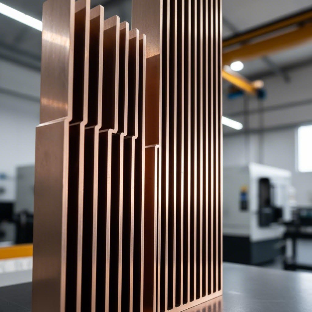
Imagine you're holding a component that can pull heat away from sensitive electronics faster than you can blink. That's essentially what finned aluminum extrusions do. These are aluminum profiles manufactured through a specialized extrusion process, featuring integrated fins that dramatically increase surface area for heat dissipation. Whether you're an engineer designing thermal solutions or a procurement professional sourcing components, understanding these profiles is essential for effective thermal management.
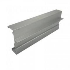
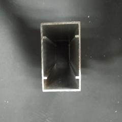
At their core, finned aluminum extrusions are continuous metal profiles where the cooling fins form as an integral part of the structure—not attached afterward, but created simultaneously during manufacturing. This single-piece construction eliminates thermal barriers between the base and fins, resulting in superior heat transfer performance compared to assembled alternatives.
The manufacturing process behind these thermal components is remarkably elegant. It begins with a cylindrical aluminum billet—typically cut to a predefined length—that gets heated to approximately 800-925°F (427-496°C). At this temperature, the aluminum becomes malleable but not molten, retaining its structural integrity while becoming soft enough to shape.
Here's where things get interesting. A hydraulic press, capable of exerting tremendous pressure (often between 100 and 15,000 tons depending on profile complexity), forces the heated billet through a precision-engineered die. This die contains the female profile of your desired heat sink extrusion shape—fins and all. As the aluminum passes through, it emerges on the other side as a continuous profile with the exact cross-sectional geometry defined by the die opening.
The extruded profile is then cooled using air or water, cut to manageable lengths, and straightened in a "puller" that also relieves internal stress. The result? A seamless extruded aluminum heat sink with fins that share perfect molecular bonding with the base—no joints, no gaps, no thermal resistance between components.
This process stands in sharp contrast to other fin attachment methods:
Extruded heatsinks eliminate these concerns entirely. The fins and base form a monolithic structure with consistent thermal conductivity throughout, ensuring heat flows unimpeded from the mounting surface to the fin tips.
When evaluating extruded heat sink profiles for your application, several dimensional characteristics determine both thermal performance and manufacturability. Understanding these parameters helps you communicate effectively with suppliers and make informed decisions.
These characteristics work together to define a profile's thermal capacity. A well-designed finned extrusion balances surface area maximization with practical manufacturing limits and airflow considerations—something we'll explore in greater depth throughout this guide.
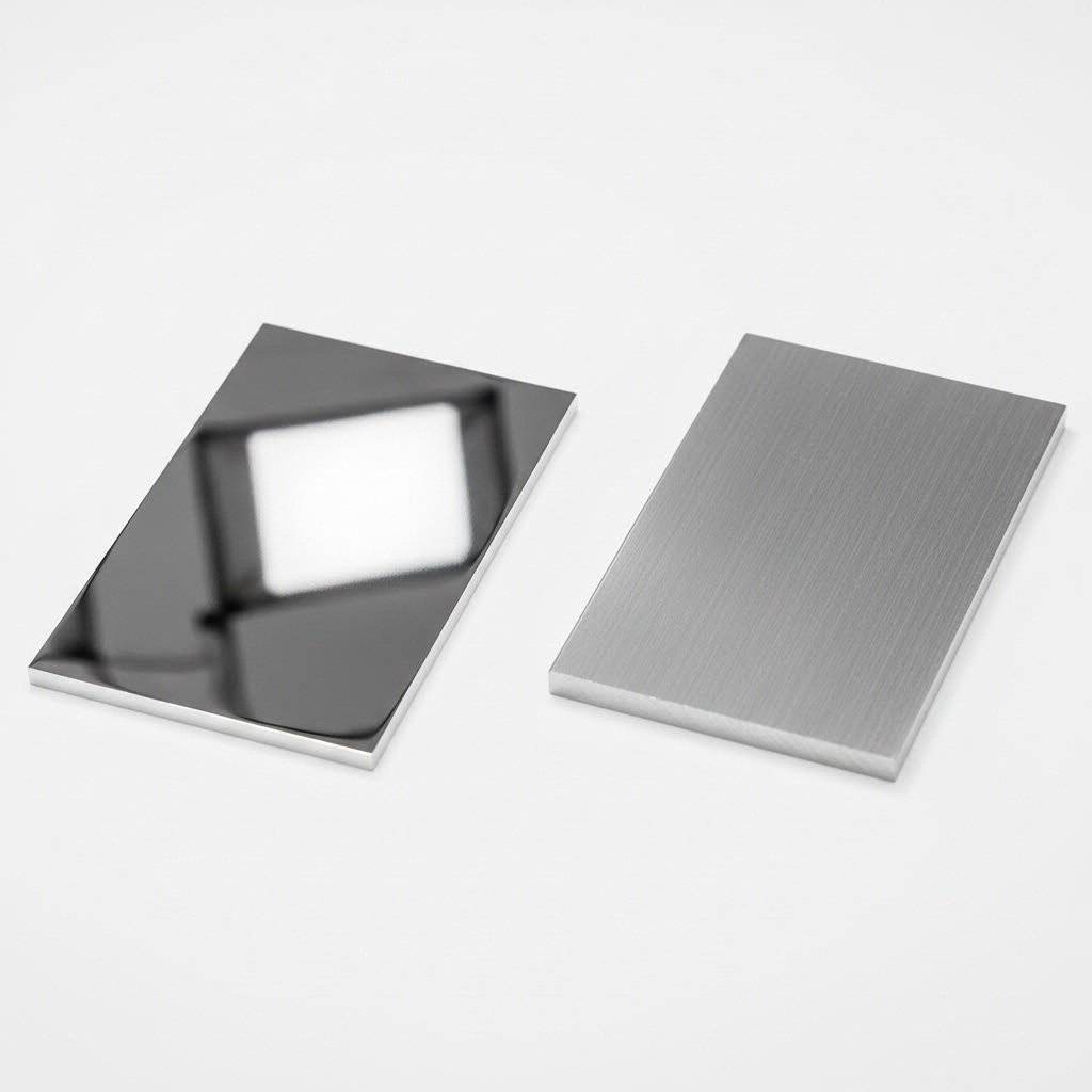
You've got the perfect fin geometry on paper—but here's the catch. The aluminum alloy you choose can make or break your thermal performance. Most suppliers mention "6063" or "6061" without explaining what these numbers actually mean for your heat dissipation needs. Let's change that.
Pure aluminum boasts an impressive thermal conductivity of 237 W/m·K, making it one of the best conductors of heat among common engineering metals. However, pure aluminum lacks the mechanical strength required for most applications. That's where aluminum alloys come in—they sacrifice a portion of that thermal conductivity in exchange for improved strength, hardness, and manufacturability. For extruded aluminum heatsink applications, two alloys dominate the landscape: 6063 and 6061.
Both 6063 and 6061 belong to the 6xxx series of aluminum alloys, meaning they're primarily strengthened through magnesium and silicon additions. However, their different compositions create distinct performance profiles that matter significantly for thermal management.
6063 aluminum—often called architectural aluminum—contains approximately 0.4% silicon and 0.7% magnesium. This composition makes it exceptionally easy to extrude, allowing manufacturers to create complex fin geometries with smooth surface finishes. More importantly for thermal applications, 6063 offers a thermal conductivity of approximately 200 W/m·K in the T6 temper—making it the superior choice when heat dissipation is your primary concern.
6061 aluminum takes a different approach. With higher magnesium content (around 0.6%) plus additions of copper (0.25%) and chromium (0.09%), this alloy prioritizes mechanical strength. Its thermal conductivity drops to roughly 170 W/m·K—about 15% lower than 6063. However, 6061 delivers significantly higher tensile and yield strength, making it the better option when aluminum fins must withstand mechanical loads or harsh operating environments.
Here's a practical comparison to guide your selection:
| Property | 6063-T6 | 6061-T6 |
|---|---|---|
| Thermal Conductivity | 200 W/m·K | 170 W/m·K |
| Tensile Strength | 241 MPa | 310 MPa |
| Yield Strength | 214 MPa | 276 MPa |
| Brinell Hardness | 73 | 95 |
| Extrudability | Excellent | Good |
| Surface Finish | Superior | Good |
| Typical Applications | LED heat sinks, electronics cooling, architectural profiles | Structural heat sinks, transportation, heavy-duty equipment |
When you're selecting extruded aluminum heat sink material, think about your priorities. Need maximum heat transfer for LED lighting or consumer electronics? Choose 6063. Designing a heat sink that must also bear mechanical loads in industrial or automotive settings? 6061's extra strength justifies its thermal conductivity trade-off.
You'll notice "T5" and "T6" designations attached to alloy specifications. These temper codes aren't marketing jargon—they describe specific heat treatment processes that fundamentally alter the material's properties.
T5 temper indicates the aluminum extrude profile was cooled from the extrusion temperature and then artificially aged. This process is less intensive than T6, resulting in moderate strength improvements while maintaining excellent formability. T5-tempered profiles work well for decorative applications or situations where the heat sink requires post-extrusion bending or shaping.
T6 temper involves solution heat treatment by artificial aging—a more rigorous process that maximizes mechanical properties. According to research published in the journal Materials, aging treatment precipitates alloying elements from the aluminum matrix, which reduces lattice distortion and actually improves thermal conductivity compared to as-quenched material.
The key insight? Heat treatment affects both strength and thermal performance. While T6 temper creates stronger material than T5, the precipitation of alloying elements during aging can enhance thermal conductivity by 15-20% compared to solution-treated conditions. This happens because dissolved alloying elements scatter heat-carrying electrons more aggressively than precipitated phases do.
For most finned aluminum extrusion applications, T6 temper offers the optimal balance—strong enough for handling and mounting, with thermal properties that approach the alloy's full potential. Understanding these material fundamentals helps you specify precisely what your application demands rather than accepting whatever a supplier happens to stock.
So you've selected the right alloy—now what? Here's where many thermal designs fall apart. The geometry of your fins matters just as much as the material they're made from. In fact, research on heat sink design consistently shows that fin spacing and configuration directly influence both heat dissipation capacity and airflow dynamics. Get the geometry wrong, and even the best aluminum alloy won't save your thermal solution.
Think of it this way: adding more fins increases surface area for heat transfer, which sounds great in theory. But pack those fins too tightly, and you're essentially choking the airflow that carries heat away. This fundamental trade-off between surface area and airflow resistance defines every heatsink extrusion profile ever designed.
Fin density—typically measured as fins per inch (FPI) or by the spacing between adjacent fins (fin pitch)—creates a delicate balancing act. Closer fin spacing dramatically increases the total surface area available for convective heat transfer. Sounds like a win, right? Not so fast.
When fins are positioned too close together, two problems emerge. First, the narrow channels between fins create significant pressure drop, restricting airflow volume through the heat sink. This becomes critical in natural convection applications where no fan forces air through the profile. Second—and this is the insight most competitors miss—the boundary layers of adjacent fins can actually merge when spacing gets too tight.
According to thermal performance research, when boundary layers merge, they create stagnant zones where hot air gets trapped between fins. Instead of fresh, cool air continuously sweeping heat away, you end up with a pocket of warm air that insulates rather than cools. The result? Your carefully designed extruded heat sink profiles actually underperform compared to a simpler design with wider spacing.
The optimal fin pitch depends heavily on whether your application uses natural or forced convection:
There's another consideration that's often overlooked: noise. Tighter fin spacing forces air through narrow channels at higher velocities, creating turbulence-induced whistling or humming—a significant concern for consumer electronics where silent operation matters. Heatsink profiles designed for laptops or gaming consoles often use wider spacing specifically to minimize acoustic signature.
Even if your thermal calculations suggest tall, thin fins packed densely together, the extrusion process itself imposes hard limits on what's actually manufacturable. Understanding these constraints helps you design profiles that perform well and can actually be produced cost-effectively.
The most critical limitation involves the aspect ratio—the relationship between fin height and the gap width between fins. According to the Aluminum Extruders Council's design guidelines, high tongue ratios (width of fin versus height) create significant challenges during extrusion. When fins are too tall relative to their thickness and spacing, the die becomes fragile and prone to breakage. The aluminum also struggles to flow evenly into deep, narrow cavities, potentially creating incomplete fills or surface defects.
For standard extrusion processes, practical aspect ratios typically max out around 10:1 (fin height to gap width). Push beyond this, and you'll face escalating die costs, slower production speeds, and higher rejection rates—all of which drive up your per-piece costs.
Here are the key geometric parameters that govern what's achievable in heatsink profiles:
One clever workaround for applications demanding extremely tall fins: bonded fin construction. Rather than extruding impossibly tall fins as a single piece, manufacturers can extrude a finned base and mechanically bond additional fin height. This sacrifices some thermal efficiency at the joint but enables fin heights that would be impossible through extrusion alone.
The bottom line? Optimal fin geometry balances thermal physics with manufacturing reality. The best-performing design on paper means nothing if it can't be extruded reliably at a reasonable cost. By understanding both the thermal trade-offs and production constraints, you can specify profiles that deliver excellent heat dissipation while remaining practical to manufacture—and that's exactly what the next section on comparing different thermal solutions will help you evaluate.
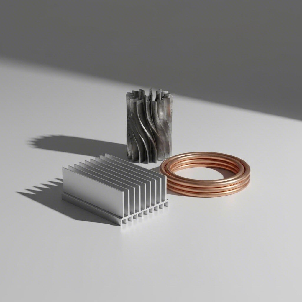
You've nailed the alloy selection and dialed in your fin geometry. But here's a question that rarely gets asked: are finned aluminum extrusions actually the right solution for your application? Or would finned tubes, copper alternatives, or bonded fin assemblies serve you better?
This isn't a rhetorical question. Different thermal challenges demand different solutions, and choosing the wrong one can mean overspending, underperforming, or both. Let's break down how these alternatives stack up so you can make an informed decision rather than defaulting to whatever your supplier happens to sell.
| Solution Type | Thermal Conductivity | Relative Cost | Weight | Manufacturing Complexity | Best Applications |
|---|---|---|---|---|---|
| Finned Aluminum Extrusions | 200 W/m·K (6063-T6) | Low-Medium | Light (2.7 g/cm³) | Low | Electronics, LED cooling, general thermal management |
| Finned Copper Tubing | 385 W/m·K | High | Heavy (8.9 g/cm³) | Medium-High | High heat flux, compact designs, liquid cooling |
| Welded Fin Tubes | Varies by material | Medium-High | Medium-Heavy | High | Boilers, heat recovery, industrial exchangers |
| Bonded Fin Heat Sinks | 170-385 W/m·K | Medium-High | Varies | Medium | High-power applications requiring tall fins |
The aluminum vs copper debate gets heated—pun intended—but the answer isn't as simple as "copper conducts better." Yes, copper's thermal conductivity of 385 W/m·K nearly doubles aluminum's 200 W/m·K. Yet aluminum dominates the heat sink market. Why?
Start with weight. Copper's density of 8.9 g/cm³ makes it roughly three times heavier than aluminum at 2.7 g/cm³. For portable electronics, automotive components, or any application where mass matters, this difference is decisive. A copper finned pipe delivering the same thermal performance as an aluminum extrusion would add significant weight—often unacceptable in modern designs prioritizing lightness.
Then there's cost. Copper typically runs three to four times the price of aluminum per pound, and that's before factoring in manufacturing. Copper's hardness makes it more challenging to machine, increasing production costs further. According to industry analysis, when you calculate cost-per-watt of cooling capacity, aluminum frequently delivers better value despite its lower conductivity.
Here's the insight that changes the equation: thermal performance isn't just about conductivity. It's about the entire thermal path from heat source to ambient air. Consider these scenarios where aluminum wins:
That said, copper finned tube solutions earn their place in specific niches. High-density server cooling, where space is extremely limited, often justifies copper's cost premium. A copper finned tube can handle intense heat loads in a smaller footprint than aluminum. Liquid cooling systems frequently use copper water blocks because the fluid interface benefits directly from copper's superior conductivity.
The practical takeaway? Don't default to copper because it "conducts better." Calculate your actual thermal requirements, factor in weight and cost constraints, then choose the material that optimizes your complete system—not just one metric.
Beyond material selection, the method of fin attachment fundamentally affects thermal performance and long-term reliability. This is where finned aluminum extrusions hold a significant advantage over alternatives—though not universally.
When fins extrude as an integral part of the profile, there's zero thermal resistance at the fin-to-base interface. Heat flows from the mounting surface through the base and into fins without encountering any gaps, joints, or bonding agents that could impede transfer. This molecular continuity makes extruded heatsinks inherently more efficient than assembled alternatives.
Compare this to mechanically attached fins:
Durafin tube and similar extruded finned tube products occupy an interesting middle ground. These use extrusion to form an aluminum sleeve with integral fins over a base tube, creating tight metallurgical contact without the interface issues of wrapped fins. They're particularly popular in harsh environments where the aluminum completely protects the underlying tube from corrosion.
So when should you choose something other than standard finned aluminum extrusions?
Choose welded or embedded fin tubes when: Your application involves extreme temperatures beyond aluminum's limits, fluid flows inside the tube, or you need fin tubes for heat exchangers in heavy industrial settings like boilers and heat recovery units.
Choose bonded fin heat sinks when: Your thermal calculations demand fin heights exceeding extrusion limits (typically 80-100mm for standard processes). High-power electronics like IGBT modules sometimes require these ultra-tall fin configurations.
Choose copper finned tube solutions when: Space is extremely constrained and you need maximum heat transfer in the smallest possible footprint, or when you're designing liquid cooling systems where copper's conductivity advantage directly benefits fluid-side heat transfer.
Stick with finned aluminum extrusions when: You're designing electronics cooling, LED thermal management, HVAC components, or any application where the combination of cost-effectiveness, light weight, and reliable thermal performance matters most. For the vast majority of thermal management challenges, extruded aluminum profiles offer the optimal balance—which is precisely why they dominate the market.
Understanding these trade-offs positions you to select the right thermal solution rather than the default one. And once you've identified finned aluminum extrusions as your answer, the next step is matching specific profile configurations to your application's unique requirements.
Now that you understand the trade-offs between different thermal solutions, here's the practical question: which finned aluminum extrusion profile actually fits your specific application? The answer depends entirely on your operating environment—heat load, available airflow, space constraints, and environmental conditions all drive profile selection in different directions.
What works brilliantly for an LED streetlight will fail spectacularly in a motor drive enclosure. A fin configuration optimized for forced-air server cooling would underperform in a naturally ventilated outdoor telecom cabinet. Let's walk through the major application categories and connect the dots between real-world requirements and fin geometry choices.
Electronic components generate concentrated heat loads that demand efficient thermal pathways. The challenge? These applications typically involve tight space constraints, weight limitations, and often aesthetic considerations that influence profile selection.
LED lighting represents one of the fastest-growing applications for finned aluminum profiles. According to industry research, LEDs generate significant heat during operation, and efficient heat dissipation is crucial for maintaining brightness, color consistency, and lifespan. A well-designed LED heat sink can extend operational life from 25,000 hours to over 50,000 hours simply by keeping junction temperatures 10-15°C lower.
Profile selection for LED applications typically favors:
Power supplies and voltage regulators present different challenges. These components generate heat across larger surface areas and often operate in enclosed spaces with minimal airflow. Finned tubing configurations or profiles with extended base plates help spread heat before transferring it to fins, preventing hot spots that could trigger thermal shutdown.
Motor drives and power electronics push thermal requirements even further. According to manufacturing specialists, motor drives and power supplies in industrial settings generate significant thermal loads that demand robust cooling solutions. These applications often benefit from:
Industrial applications demand a fundamentally different approach to profile selection. Here, durability, corrosion resistance, and long-term reliability often outweigh pure thermal efficiency. When selecting fin tubes for heat exchangers, environmental conditions become the primary design driver.
HVAC systems represent a massive market for finned aluminum profiles. Finned-pack heat exchangers for heating, cooling, and energy recovery applications use specialized geometries optimized for air-side performance. These systems typically feature:
Industrial equipment cooling spans applications from factory automation to heavy machinery. Finned pipe configurations excel in environments where traditional finned flat profiles would be impractical—wrapped around cylindrical housings, integrated into process piping, or configured for liquid-to-air heat exchange.
Fin pipes in industrial settings often prioritize:
Automotive thermal management has evolved dramatically with vehicle electrification. Aluminum extrusion heat sinks now cool not just engine control units but also battery packs, inverters, and onboard chargers in electric and hybrid vehicles. These applications demand:
The common thread across all these applications? Matching profile specifications to actual operating conditions rather than theoretical maximums. A thermal engineer designing for forced-air server cooling makes fundamentally different choices than one specifying heat exchangers for a rooftop HVAC unit. Understanding your specific requirements—heat load magnitude, airflow type and velocity, environmental exposure, and maintenance constraints—guides you toward profiles that perform reliably in the real world, not just on paper.
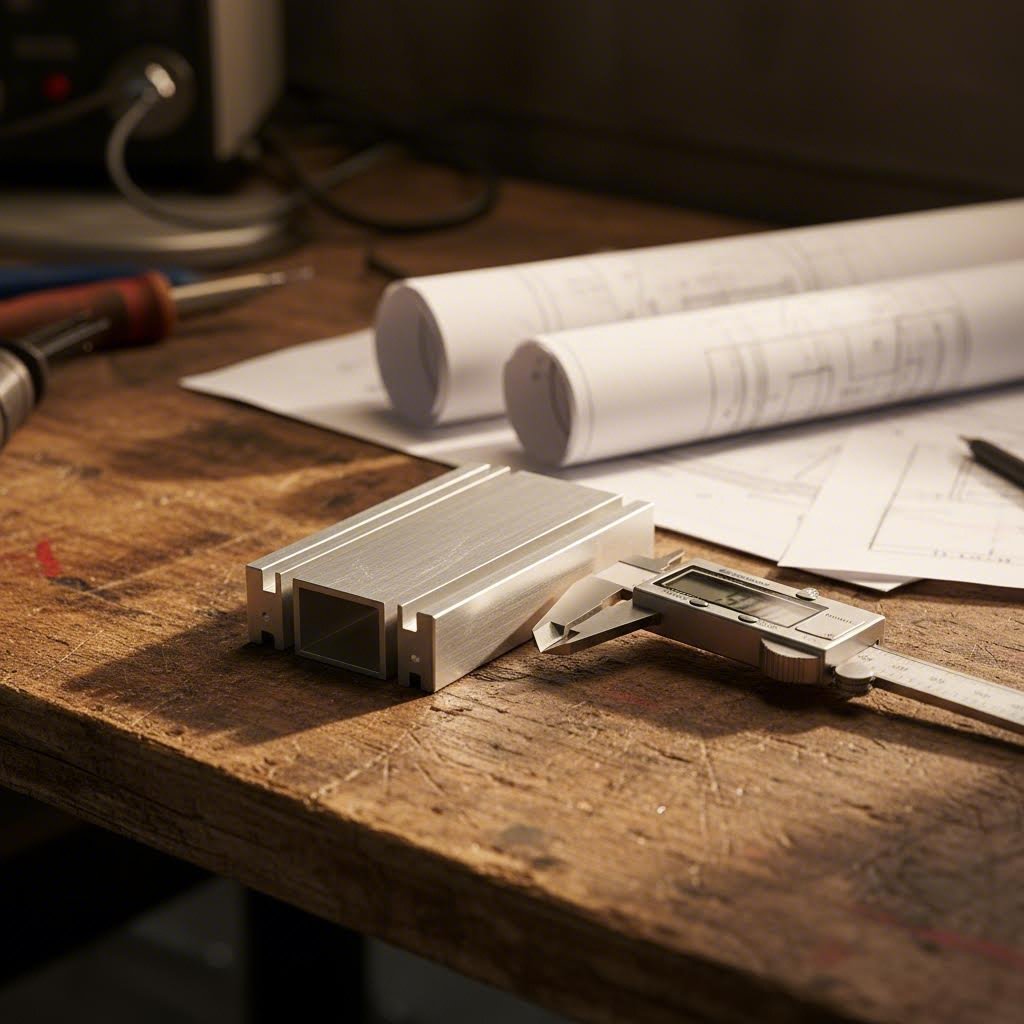
You've explored applications and understand the physics—but here's where theory meets practice. How do you actually translate your thermal requirements into a specific profile specification? This is where most engineers and procurement professionals get stuck, and where most supplier content falls silent.
The selection process isn't about finding the "best" extrusion heat sink. It's about finding the right one for your specific combination of heat load, airflow conditions, physical constraints, and environmental factors. Get any of these wrong, and you'll either overspend on capacity you don't need or end up with a thermal solution that can't keep up with your demands.
Let's walk through a systematic approach that works whether you're specifying a single prototype or sourcing thousands of units.
Before browsing supplier catalogs, you need to know exactly what thermal performance your application demands. This starts with understanding three fundamental values: your heat load, your maximum allowable temperature, and your ambient operating conditions.
According to thermal engineering research from Boyd Corporation, the relationship between these parameters determines your required thermal resistance—the single most important specification when selecting an aluminum extrusion heat sink.
Here's the core equation that governs heat sink selection:
Required Thermal Resistance (Rsa) = (Tj - Ta) / Q - Rjc - Rcs
Sounds complex? Let's break it down:
Here's a practical example. Imagine you're cooling a power semiconductor that dissipates 25W, has a maximum junction temperature of 125°C, and operates in a 45°C ambient environment. The device datasheet shows Rjc = 1.5°C/W, and you're using a quality thermal compound with Rcs = 0.5°C/W.
Your required heat sink thermal resistance would be:
Rsa = (125 - 45) / 25 - 1.5 - 0.5 = 3.2 - 2.0 = 1.2°C/W
This means you need an extruded fin tube or profile with a thermal resistance of 1.2°C/W or lower. Any heat sink exceeding this value will allow your component to overheat under maximum load.
With your required thermal resistance calculated, the next step is identifying profiles that can deliver this performance under your actual operating conditions. This is where airflow type becomes critical.
Industry research shows that volumetric thermal resistance—measured in cm³·°C/W—varies dramatically based on cooling method:
| Flow Condition | Volumetric Resistance Range | Optimal Fin Spacing |
|---|---|---|
| Natural Convection | 500-800 cm³·°C/W | 6.5-13mm depending on fin length |
| Low Forced (1.0 m/s) | 150-250 cm³·°C/W | 4.0-7.0mm |
| Medium Forced (2.5 m/s) | 80-150 cm³·°C/W | 2.5-5.0mm |
| High Forced (5.0 m/s) | 50-80 cm³·°C/W | 2.0-3.5mm |
Notice how tighter fin spacing becomes viable—and even optimal—as airflow velocity increases. This explains why server heat sinks look dramatically different from passively cooled LED fixtures.
Follow this step-by-step process to move from thermal requirements to profile specification:
One factor that's frequently overlooked: spreading resistance. When your heat source is significantly smaller than the heat sink base, additional thermal resistance of 5-30% can occur as heat spreads from the concentrated source across the larger base area. Thicker bases help mitigate this—but add weight and cost.
Quality factors also affect real-world performance. Tight dimensional tolerances ensure consistent fin spacing and proper mating with mounting surfaces. Surface finish quality impacts both thermal interface effectiveness and radiation heat transfer. When evaluating suppliers, ask about:
The selection process ultimately balances thermal performance against practical constraints. A profile that exceeds your thermal requirements but doesn't fit your enclosure—or costs three times your budget—isn't the right choice. Conversely, squeezing a marginally adequate heat sink into a tight space creates reliability risks that surface only after deployment.
With your requirements clearly defined and a shortlist of candidate profiles identified, the next consideration becomes surface treatments and installation practices that maximize the thermal performance of your selected extrusion.
You've selected the perfect profile with optimal fin geometry—but here's what most suppliers won't tell you. The surface treatment you choose and how you mount that extrusion can make a 20-30% difference in real-world thermal performance. Ignore these factors, and you'll leave significant cooling capacity on the table.
Think of surface treatments as the finishing touches that transform a raw aluminum profile into a high-performance thermal solution. And proper installation? That's the difference between theoretical specifications and actual results in your application. Let's cover both.
Raw aluminum extrusions work fine in controlled environments—but real-world applications rarely stay that cooperative. Humidity, dust, chemicals, UV exposure, and thermal cycling all degrade unprotected aluminum over time. More importantly for thermal applications, surface treatments can actually improve heat dissipation, not just protect against corrosion.
Here's the insight most competitors miss: according to thermal research from Gabrian, unfinished aluminum has an emissivity of approximately 0.05, while anodized aluminum reaches around 0.85. That's a 17-fold improvement in radiation heat transfer capability.
Why does this matter? Heat sinks dissipate thermal energy through two mechanisms: convection (air carrying heat away) and radiation (electromagnetic energy emission). In passive cooling applications without forced airflow, radiation can account for 25-40% of total heat dissipation. Boosting emissivity through anodizing dramatically enhances this radiation component.
Here are the primary surface treatment options for extruded aluminum tubes and finned profiles, along with their specific benefits:
The key takeaway? For thermal-critical applications, anodizing delivers the best of both worlds—improved corrosion protection and enhanced heat dissipation. For applications where aesthetics or environmental protection take priority over thermal performance, powder coating or PVDF provide superior options. Never paint or powder coat heat sinks in high-performance thermal applications where every degree of cooling matters.
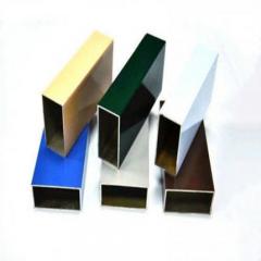
One nuance worth noting: color choice in anodized finishes doesn't significantly affect thermal performance. Research confirms that whether you choose black, blue, green, or other dyed anodized finishes, heat transfer remains essentially unchanged. The emissivity improvement comes from the oxide layer's microscopic texture and increased surface area—not the dye color. Choose colors based on aesthetic requirements without thermal penalty.
Even the best extruded tubing aluminum profile with perfect surface treatment will underperform if installed incorrectly. The interface between your heat source and the extrusion base represents the critical thermal bottleneck—and it's where most real-world performance issues originate.
Imagine two machined metal surfaces pressed together. They look flat to the naked eye, but microscopically, only 1-2% of the surfaces actually make contact. The rest consists of tiny air gaps—and air is a terrible thermal conductor. This is why thermal interface materials (TIMs) and proper mounting pressure are essential.
Follow these installation practices to ensure your finned aluminum extrusions deliver their rated performance:
For long-term reliability, consider these maintenance factors during the design phase:
The difference between a properly installed heat sink and a carelessly mounted one can exceed 0.5°C/W in thermal resistance—enough to mean the difference between a reliable product and one that experiences premature failures. Take installation as seriously as profile selection, and your thermal solution will perform as designed for years of service.
Even with proper selection, surface treatment, and installation, thermal challenges can emerge during operation. Understanding how to diagnose and address these issues ensures your finned extrusion continues performing at its best.
Your finned aluminum extrusion looked perfect on paper. The thermal calculations checked out. Installation best practices. Yet three months into deployment, you're seeing thermal shutdowns—or worse, premature component failures. What went wrong?
The reality is that even well-designed thermal solutions encounter problems in real-world operation. Dust accumulates. Mounting hardware loosens. Environmental conditions exceed initial specifications. Knowing how to diagnose and address these challenges quickly separates minor inconveniences from costly system failures.
When an extruded heatsink stops performing as expected, the symptoms usually manifest as elevated component temperatures, thermal throttling, or unexpected shutdowns. But symptoms don't tell you the root cause—and treating the wrong problem wastes time and money.
Start your diagnosis by asking: did this work before, or was performance always marginal? Systems that degraded over time point toward fouling, interface degradation, or environmental changes. Systems that never performed correctly suggest specification mismatches or installation errors.
Here are the most common thermal performance problems with their causes and solutions:
One diagnostic technique that often reveals hidden problems: thermal imaging. An infrared camera quickly identifies hot spots, blocked airflow patterns, and interface contact issues that aren't visible through temperature sensors alone. Even inexpensive thermal cameras can detect 5-10°C variations that pinpoint problem areas.
Aluminum fins are surprisingly delicate. Those thin structures that maximize surface area for heat transfer can bend, crush, or break during handling, shipping, and installation. Damaged fins don't just look unprofessional—they reduce effective cooling surface area and can obstruct airflow between adjacent fins.
Mechanical issues typically fall into three categories:
Environmental challenges present longer-term reliability concerns. According to corrosion research, environmental factors including moisture, airborne salts, and chemical exposure can significantly degrade finned aluminum components over time.
The most cost-effective approach? Prevention through proper specification. Understanding your operating environment upfront—and communicating those conditions to your supplier—enables selection of appropriate alloys, surface treatments, and fin geometries that resist problems before they occur. When issues do arise, early detection through regular inspection prevents minor problems from becoming major failures.
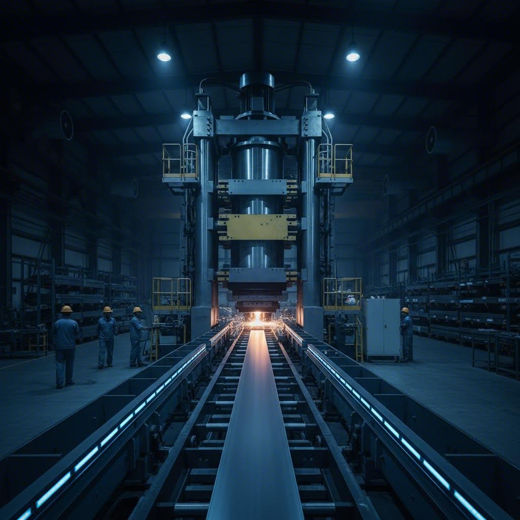
You've defined your thermal requirements, selected the right profile specifications, and understand surface treatment options. Now comes the question that separates prototype success from production reality: who actually manufactures your finned aluminum extrusions, and what should you expect from the process?
Working with custom extrusion manufacturers isn't like ordering off-the-shelf components. Whether you need unique extrusions for specialized thermal applications or aluminium finned tubes with specific geometries, the journey from concept to finished parts involves multiple stages—each with its own timeline, cost considerations, and potential pitfalls. Understanding this process helps you set realistic expectations and choose suppliers who can actually deliver.
Every custom finned extrusion starts with a die—the precision-machined steel tool that shapes aluminum as it's forced through under tremendous pressure. According to industry experts at Star Extruded Shapes, die development begins with digital design using specialized software like AutoCAD or SolidWorks, enabling faster quoting, streamlined prototyping, and reduced time to market.
Here's what the custom die development process typically involves:
Die costs vary significantly based on profile complexity. Simple rectangular fin patterns might cost $500-1,500, while intricate geometries for aluminium extrusion tube configurations or high-density fin arrays can exceed $3,000-5,000. These are one-time costs typically amortized across your production volume—but they represent a real investment that makes supplier selection critical.
One important consideration: die ownership. Clarify upfront whether you own the die after paying for its development or whether it remains supplier property. Ownership matters if you ever need to transfer production to a different manufacturer.
Not all fin tubes manufacturers are created equal. The difference between a capable partner and a problematic supplier often becomes apparent only after you've committed—which is exactly when you don't want surprises. Evaluate potential suppliers systematically before placing orders.
Industry research identifies press capacity as the foundational capability that determines what profiles a supplier can produce:
A supplier with multiple press capacities offers flexibility as your requirements evolve. For example, Shengxin Aluminium operates 35 extrusion presses ranging from 600T to 5500T—providing the range needed to handle everything from delicate electronics heat sinks to substantial industrial heat exchanger profiles.
Beyond press capacity, evaluate these critical capabilities:
Shengxin Aluminium exemplifies what comprehensive manufacturers offer: over 30 years of industry experience, state-of-the-art CNC machining centers for precise secondary operations, and an extensive array of surface treatments including custom-color anodizing, powder coating, PVDF, and micro-arc oxidation. Their end-to-end support—from die development through mass production—demonstrates the integrated capability that simplifies complex projects.
When evaluating potential suppliers, ask these essential questions:
Regarding minimum order quantities (MOQs), expect significant variation among suppliers. Custom aluminium finned tubes profiles typically require MOQs ranging from 500kg to 2,000kg for initial orders, with lower minimums possible for repeat orders using existing dies. Some suppliers accommodate prototype quantities at premium pricing—worth exploring if you need to validate designs before committing to production volumes.
Typical project timelines break down as follows:
| Stage | Typical Duration | Variables Affecting Timeline |
|---|---|---|
| Die Manufacturing | 10-20 days | Profile complexity, supplier capacity |
| Extrusion Production | 7-15 days | Order quantity, press availability |
| Surface Finishing | 5-10 days | Treatment type, color matching requirements |
| Total Project | 4-6 weeks | Integration of services, shipping logistics |
These timelines assume standard projects without major complications. Complex profiles, specialized alloys, or peak-season production schedules can extend delivery dates significantly.
Strong technical communication differentiates professional suppliers from order-takers. Capable manufacturers provide DFM feedback on your drawings, offer feasibility and cost optimization suggestions, and share inspection photos and reports before shipment. They prevent issues proactively rather than reacting after defects occur.
The investment you make in supplier evaluation pays dividends throughout your project—and across future orders. A manufacturer with comprehensive capabilities, transparent communication, and proven quality systems transforms custom finned aluminum extrusions from a procurement headache into a competitive advantage for your thermal management solutions.
Finned aluminum extrusions serve as highly efficient heat dissipation solutions across multiple industries. Primary applications include electronics cooling for LED lighting, power supplies, and motor drives; HVAC heat exchangers for heating and cooling systems; industrial equipment thermal management; and automotive applications including battery pack cooling for electric vehicles. The integrated fin design provides superior thermal contact compared to mechanically attached alternatives, making them ideal wherever reliable heat transfer is critical.
The key difference lies in their thermal conductivity versus mechanical strength trade-off. 6063 aluminum offers thermal conductivity of approximately 200 W/m·K with excellent extrudability and surface finish—making it the preferred choice for maximum heat dissipation in LED heat sinks and electronics cooling. 6061 aluminum provides higher tensile strength (310 MPa vs 241 MPa) but lower thermal conductivity at 170 W/m·K. Choose 6061 when your heat sink must also bear mechanical loads in industrial or automotive applications.
Calculate required thermal resistance using the formula: R(sa) = (Tj - Ta) / Q - Rjc - Rcs. Here, Tj is your component's maximum junction temperature, Ta is ambient temperature, Q is heat dissipation in watts, Rjc is junction-to-case resistance from the component datasheet, and Rcs is interface resistance from your thermal compound. For example, a 25W device with 125°C max temperature in 45°C ambient with 2.0°C/W total interface resistance requires a heat sink rated at 1.2°C/W or lower.
Optimal fin spacing depends on your cooling method. Natural convection applications require wider spacing of 6-10mm to allow buoyancy-driven airflow development and prevent boundary layer interference. Forced convection with fans permits tighter 3-6mm spacing since fans overcome pressure drop penalties. High-dust environments benefit from wider spacing to reduce clogging. The key insight: pack fins too tightly and merged boundary layers create stagnant hot air pockets that reduce cooling efficiency despite increased surface area.
Yes, anodizing significantly improves thermal performance through enhanced emissivity. Unfinished aluminum has emissivity of approximately 0.05, while anodized aluminum reaches around 0.85—a 17-fold improvement in radiation heat transfer capability. In passive cooling applications without forced airflow, radiation accounts for 25-40% of total heat dissipation. Black anodizing maximizes this benefit while also providing corrosion resistance. Importantly, the color choice (black, blue, or other dyed finishes) doesn't significantly affect thermal performance—the improvement comes from the oxide layer's texture.



 Інтернет-сервіс
 0086 136 3563 2360
 sales@sxalu.com
 +86 136 3563 2360
 Українська
 English
 français
 Deutsch
 русский
 español
 português
 العربية
 ไทย
ไทย Việt
Việt