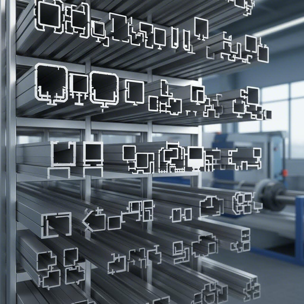
When you're designing a component that must fit precisely with other parts, how do you know the extruded profile you receive will actually match your specifications? This is where aluminum extrusion tolerances come into play. Simply put, these tolerances are guidelines that define the allowable deviations from specified dimensions within which extruded parts must fall to be considered acceptable. They establish the boundaries between a profile that works perfectly and one that causes assembly headaches.
To fully grasp the aluminum extrusion definition, think of it as a manufacturing process where heated aluminum billets are pushed through a shaped die to create profiles with consistent cross-sections. The aluminium extrusion meaning extends beyond just shaping metal—it encompasses the precise control of every dimension throughout production. Tolerances serve as the critical quality parameters that ensure each extruded piece functions as intended without requiring costly modifications.
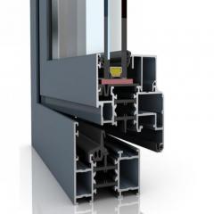
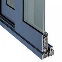
Imagine ordering thousands of standard aluminum extrusion profiles for a window frame assembly, only to discover they don't fit together properly on your production line. This scenario highlights exactly why understanding aluminum extrusion dimensions and their acceptable variations matters so much.
Tolerances provide the parameters within which extruders must operate. They protect three essential aspects of your final product:
For engineers, designers, and procurement professionals, this aluminum extrusion design guide serves as your bridge between raw specification data and practical application. Whether you're reviewing ANSI H35.2-2024 tables or communicating requirements to suppliers, understanding these principles prevents miscommunication and production delays.
Standard tolerances for aluminum extrusion are established by technical committees from The Aluminum Association and the American National Standards Institute. These organizations continuously update their standards to reflect technological advancements in extrusion processes and evolving industry requirements.
Proper tolerance specification is one of the main drivers of cost efficiency. If tolerances are too loose, parts won't fit or function correctly. If they're too tight, you may not be able to produce them while maintaining healthy profit margins.
This balance between precision and practicality defines successful extrusion projects. According to tolerance analysis research, optimizing tolerances to match real-world variation reduces defective parts, minimizes scrap rates, and decreases rework cycles. The result? Lower labor and material costs without sacrificing quality.
Throughout this comprehensive guide, you'll gain practical knowledge spanning the entire tolerance specification workflow—from initial design considerations through final ordering. You'll learn to distinguish between standard and precision tolerance classes, understand how profile complexity affects achievable accuracy, and discover the common mistakes that lead to costly rework. By the end, you'll have the confidence to specify aluminum extrusion tolerances that deliver exactly the parts you need.
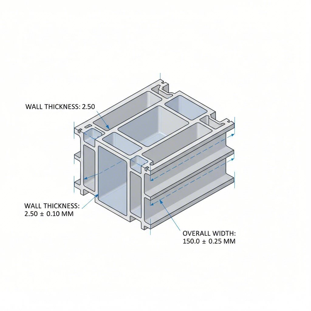
Ever looked at an extrusion specification sheet and felt overwhelmed by the various tolerance categories listed? You're not alone. Understanding the different types of aluminum extrusion tolerances is essential for specifying profiles that meet your exact requirements. Each tolerance type addresses a specific aspect of profile geometry, and together they define the overall quality and usability of your extruded parts.
Industry standards like ANSI H35.2 serve as the foundation for these specifications. Originally developed by The Aluminum Association's Technical Committee in 1949 and continuously refined since then, these tolerances represent the maximum deviation from specified dimensions that may be expected in any individual piece. For most pieces, the actual deviation will be less than the tolerance shown.
Cross-sectional dimension tolerances govern the actual measurements of your profile's features—wall thicknesses, widths, heights, and the spaces between elements. These are typically the first tolerances engineers consider because they directly impact fit and function.
According to Aluminum Association standards, cross-sectional tolerances are divided into two main categories:
The circumscribing circle diameter—the smallest circle that completely encloses your profile's cross-section—significantly affects applicable tolerances. Profiles fitting within a 10-inch diameter circle have tighter tolerance capabilities than larger profiles. For example, a 1-inch dimension on a profile with a circumscribing circle under 10 inches carries a standard tolerance of ±0.012 inches, while the same dimension on a larger profile permits ±0.019 inches.
When reviewing specifications like those found in ASTM B221 PDF documentation or aerospace standards such as AMS-QQ-A-225/8 and AMS-QQ-A-200/3, you'll find these same foundational principles apply across various material grades and applications.
Beyond cross-sectional dimensions, several geometric tolerances define how your profile behaves along its length. These become increasingly critical as extrusion lengths increase.
Straightness tolerances control how much a profile can bow or curve along its length. The standard formula is straightforward: multiply the measured length in feet by a factor that depends on profile thickness and temper. For most profiles with thicknesses of 0.095 inches and over, this factor is 0.0125 inches per foot of measured length. Thinner profiles (under 0.094 inches) may allow 0.050 inches per foot.
Twist tolerances address the rotational deviation along a profile's length. Imagine placing your extrusion on a flat surface—twist measures how much one end rotates relative to the other. The tolerance is expressed in degrees multiplied by the measured length, with maximum limits to prevent excessive rotation even on very long pieces. For profiles up to 1.499 inches wide, the standard is 1 degree per foot with a 7-degree maximum. Wider profiles get progressively tighter limits.
Angular tolerances govern the relationship between adjacent surfaces forming an angle. The allowable deviation from specified angles depends on both the minimum leg thickness and the ratio of leg length to metal thickness. Standard tolerances range from 1 degree for thicker sections to 2 degrees where leg length significantly exceeds thickness.
Flatness tolerances ensure flat surfaces remain planar without waviness or bowing. The standard for surfaces up to 1 inch wide is 0.004 inches maximum deviation. For wider surfaces, multiply 0.004 inches by the width in inches. Hollow profiles typically allow slightly more deviation—0.006 inches for the narrowest surfaces—because internal voids make perfect flatness more difficult to achieve.
| Tolerance Type | What It Measures | Typical Range | Critical Applications |
|---|---|---|---|
| Cross-Sectional Dimension | Wall thickness, width, height, and space dimensions | ±0.006" to ±0.280" depending on size and profile type | Mating parts, assembly fit, structural connections |
| Straightness | Bow or curve along profile length | 0.0125" to 0.050" per foot of length | Linear assemblies, tracks, framing systems |
| Twist | Rotational deviation along length | 0.25° to 1° per foot; 3° to 7° maximum total | Door frames, window systems, structural members |
| Angular | Deviation from specified angles between surfaces | ±1° to ±2° depending on geometry | Corner joints, bracket mounting, precision assemblies |
| Flatness | Surface planarity across width | 0.004" to 0.016" per inch of width | Sealing surfaces, aesthetic panels, heat sinks |
These tolerance categories don't operate in isolation—they work together to define your profile's overall quality. A profile might meet all dimensional tolerances perfectly yet fail if twist exceeds acceptable limits for your application. Similarly, achieving tight cross-sectional tolerances becomes more challenging when straightness requirements are extremely demanding, as the correction processes can affect dimensions.
The interplay between these tolerances explains why aluminum extrusion design requires careful consideration of which parameters truly matter for your application. As you'll discover in the following sections, specifying the right tolerance class for each category helps you achieve the quality you need without unnecessarily inflating costs.
Here's a question that can significantly impact your project budget: do you actually need precision tolerances, or are standard tolerances perfectly adequate for your application? Many engineers default to specifying tighter tolerances assuming "tighter equals better," but this assumption can inflate costs by 30% to 200% without adding any functional value. Understanding the distinction between these tolerance classes—and when each is appropriate—helps you make smarter specification decisions.
Standard aluminum extrusions follow the baseline tolerances established in industry standards like ANSI H35.2. These tolerances represent what competent extruders can reliably achieve using normal production processes and quality controls. Precision tolerances, by contrast, demand significantly tighter dimensional control that requires specialized equipment, slower production speeds, and enhanced inspection protocols.
Standard tolerances work exceptionally well for the vast majority of aluminum extrusion applications. If your profiles don't require ultra-tight fits or aren't subject to extreme performance demands, you're likely over-specifying by requesting precision tolerances.
According to industry tolerance guidelines, standard tolerances are appropriate when parts don't need to fit tightly together, when minor dimensional variations won't affect functionality, and when aesthetic consistency matters more than absolute precision. These conditions describe most real-world applications.
Standard aluminium extrusions typically achieve tolerances of ±0.020 to ±0.030 inches depending on profile size and complexity. For many assemblies, this level of accuracy is more than adequate. Consider the following applications where standard tolerances excel:
A well-designed aluminium extrusion design guide will emphasize that standard tolerances represent the sweet spot between quality and economy. These tolerances evolved over decades of industry experience to reflect what's achievable without extraordinary measures—and what's acceptable for typical applications.
Precision aluminum extrusion tolerances become necessary only when your application genuinely demands them. These tighter specifications—sometimes as precise as ±0.005 to ±0.006 inches—are reserved for situations where dimensional variation creates functional problems or safety concerns.
Applications that typically require precision tolerances include:
The cost implications of specifying precision tolerances are substantial. According to manufacturing cost research, moving from standard to precision tolerances can increase costs by 2x to 5x. Several factors drive these increases:
Before specifying precision tolerances, ask yourself these evaluation questions:
The most expensive tolerance is often the one that provides no functional benefit. Smart tolerance specification means distinguishing between dimensions that truly require tight control and those where standard variations are perfectly acceptable. This disciplined approach delivers quality where it matters while avoiding unnecessary costs that erode your project's economics.
Understanding how your profile's geometry affects achievable tolerances adds another layer to this decision-making process—a topic we'll explore next.
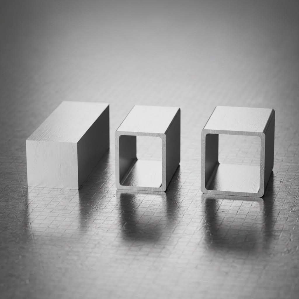
Have you ever wondered why some aluminum profiles hold tighter tolerances than others, even when manufactured by the same extruder? The answer lies in profile complexity. The geometry of your cross-section directly determines what's achievable—and understanding this relationship helps you set realistic expectations while designing profiles that meet your precision requirements.
Profile aluminum extrusion comes in three fundamental categories: solid, semi-hollow, and hollow. Each type presents distinct manufacturing challenges that affect dimensional control. Recognizing these differences before finalizing your design prevents specification frustrations and helps you communicate effectively with suppliers about what's truly achievable.
Solid profiles represent the simplest extrusion geometry and consistently achieve the tightest tolerances. Why? Because the aluminum flows through a single-piece die without internal obstructions, creating uniform pressure distribution and predictable material behavior throughout the extrusion process.
When you're working with solid shapes—bars, angles, channels, or custom configurations without enclosed voids—you benefit from several manufacturing advantages:
According to Aluminum Association tolerance standards, solid profiles with circumscribing circle diameters under 10 inches can achieve standard tolerances as tight as ±0.006 inches for metal dimensions up to 0.124 inches. Even larger solid profiles maintain respectable precision—a 2-inch dimension on a solid bar typically holds ±0.024 inches under standard conditions.
Aluminum extrusion round bars and other simple solid geometries represent the benchmark for achievable tolerances. If your application demands the tightest possible dimensional control, designing with solid cross-sections gives you the best foundation to work from.
Aluminum tube extrusion and other hollow profiles present fundamentally different manufacturing challenges. Creating enclosed voids requires porthole or bridge dies—complex two-piece tools where aluminum must flow around internal supports (called bridges or mandrels) and then reweld before exiting the die. This added complexity introduces variables that affect tolerance achievement.
Consider what happens during aluminum extrusion tube production: the metal splits to flow around the mandrel supports, then reunites under tremendous pressure. The weld seams, while metallurgically sound, create slight flow variations. The internal void makes wall thickness harder to control because you're balancing pressure from both outside and inside surfaces simultaneously.
Several factors make hollow profiles more tolerance-sensitive:
For aluminum tube profiles, industry tolerance tables specify that wall thickness tolerances must often be negotiated between purchaser and supplier when one wall is three times thicker than the opposite wall. This reflects the real-world difficulty of controlling asymmetric hollow geometries.
Semi-hollow profiles occupy the middle ground—and sometimes present the trickiest tolerance challenges. These shapes have partially enclosed areas (like a C-channel with a narrow opening) characterized by their "tongue ratio." This ratio compares the depth of the partially enclosed area to the width of its opening. Higher tongue ratios mean more difficult extrusion and wider tolerance requirements.
When tongue ratios exceed 3:1, the thin "tongue" of the die becomes increasingly fragile and prone to deflection under extrusion pressure. This deflection translates directly to dimensional variation in your finished profile. Curved extruded aluminum shapes with semi-hollow features face compounded challenges when post-extrusion bending is required.
| Profile Type | Typical Dimensional Tolerance Range | Key Design Considerations |
|---|---|---|
| Solid | ±0.006" to ±0.054" depending on dimension and circumscribing circle diameter | Simplest to manufacture; most consistent results; best choice when tight tolerances are critical; post-machining most effective |
| Semi-Hollow | ±0.008" to ±0.080" depending on tongue ratio and wall thickness | Tongue ratio significantly affects achievable tolerances; keep ratios below 3:1 when possible; wall thickness at tongue root affects die life |
| Hollow | ±0.010" to ±0.120" for cross-sectional dimensions; wall eccentricity ±10% of mean wall thickness | Porthole die required; wall thickness uniformity challenging; Class 1 hollow profiles (round voids ≥1" diameter with symmetric weight distribution) achieve tighter tolerances |
The circumscribing circle diameter—that smallest circle enclosing your entire profile cross-section—serves as a key tolerance determinant across all profile types. According to Aluminum Association Table 11.2, profiles break into two major categories: those with circumscribing circles under 10 inches, and those 10 inches and larger. Larger circumscribing circles mean proportionally wider tolerances across all dimension categories.
For example, a 0.500-inch metal dimension on a profile with a circumscribing circle under 10 inches carries a standard tolerance of ±0.009 inches. That same dimension on a profile with a 12-inch circumscribing circle permits ±0.017 inches—nearly double the variation.
Wall thickness variations compound these challenges. Thinner walls deflect more during extrusion, making tolerances harder to maintain. The flatness tolerance tables reflect this reality: surfaces formed by metal less than 0.125 inches thick allow more deviation than those formed by heavier sections. When designing profiles with varying wall thicknesses, expect the thinnest sections to exhibit the widest tolerance variations.
Smart profile design accounts for these realities from the start. By understanding how profile complexity affects your tolerance capabilities, you can make informed decisions about geometry, work with your supplier to establish realistic specifications, and identify where secondary machining might be necessary to achieve critical dimensions.
Does your choice of aluminum alloy actually affect the tolerances you can achieve? Absolutely—and this often-overlooked factor can make the difference between a profile that meets specifications effortlessly and one that struggles to stay within acceptable limits. Material selection isn't just about strength and corrosion resistance; it directly influences how aluminum flows through the die and how dimensionally stable your finished parts remain.
Understanding the relationship between alloy properties and tolerance capabilities helps you make smarter material choices during the design phase. Whether you're specifying extruded aluminum bar stock or complex custom profiles, the alloy-tolerance connection deserves careful consideration.
The 6000-series aluminum alloys dominate extrusion applications, with 6063 and 6061 representing the two most popular choices. While both contain magnesium and silicon as primary alloying elements, their different compositions create distinct extrusion behaviors that affect achievable tolerances.
Alloy 6063 is often called the "architectural alloy" because its excellent extrudability makes it ideal for complex decorative profiles. According to extrusion tolerance research, the mechanical properties of each alloy significantly impact dimensional control during manufacturing. Softer alloys flow more uniformly through intricate die geometries, resulting in more consistent wall thicknesses and tighter tolerances on complex shapes.
Key differences between these popular alloys include:
When tolerance requirements are demanding—particularly on hollow or semi-hollow profiles with thin walls—6063 often delivers better results. The alloy's lower strength actually becomes an advantage during extrusion because the aluminum flows more readily into fine details and tight corners. For aluminum bar extrusions where strength takes priority over complex geometry, 6061 remains the preferred choice despite its tighter processing window.
Temper designation tells you how an alloy has been processed after extrusion, and this processing directly affects dimensional stability. The heat treatment cycles that create different tempers can introduce dimensional changes that must be factored into your tolerance calculations.
According to heat treatment documentation, the T5 and T6 tempers represent the most common choices for extruded aluminum, yet they're produced through fundamentally different processes. T5 material is cooled directly from the extrusion temperature and then artificially aged. T6 material undergoes a separate solution heat treatment—heating to approximately 980°F, holding, then water quenching—before aging.
These processing differences create measurable tolerance implications:
The aging process itself—whether at 325°F for eight hours or 400°F for one hour—causes slight dimensional changes as alloying elements form strengthening precipitates within the aluminum matrix. Post-extrusion treatment research confirms that aging can enhance strength but may also cause slight dimensional variations that must be anticipated in critical applications.
For aluminum extrusion bars and profiles where dimensional stability matters most, consider these practical guidelines:
The interplay between alloy selection and temper designation creates a matrix of tolerance capabilities that experienced extruders understand well. When your application demands specific tolerances on aluminum extrusion bar stock or complex profiles, discuss both alloy and temper options with your supplier early in the design process. This collaborative approach helps identify the material combination that delivers your required tolerances while meeting strength and other performance specifications.
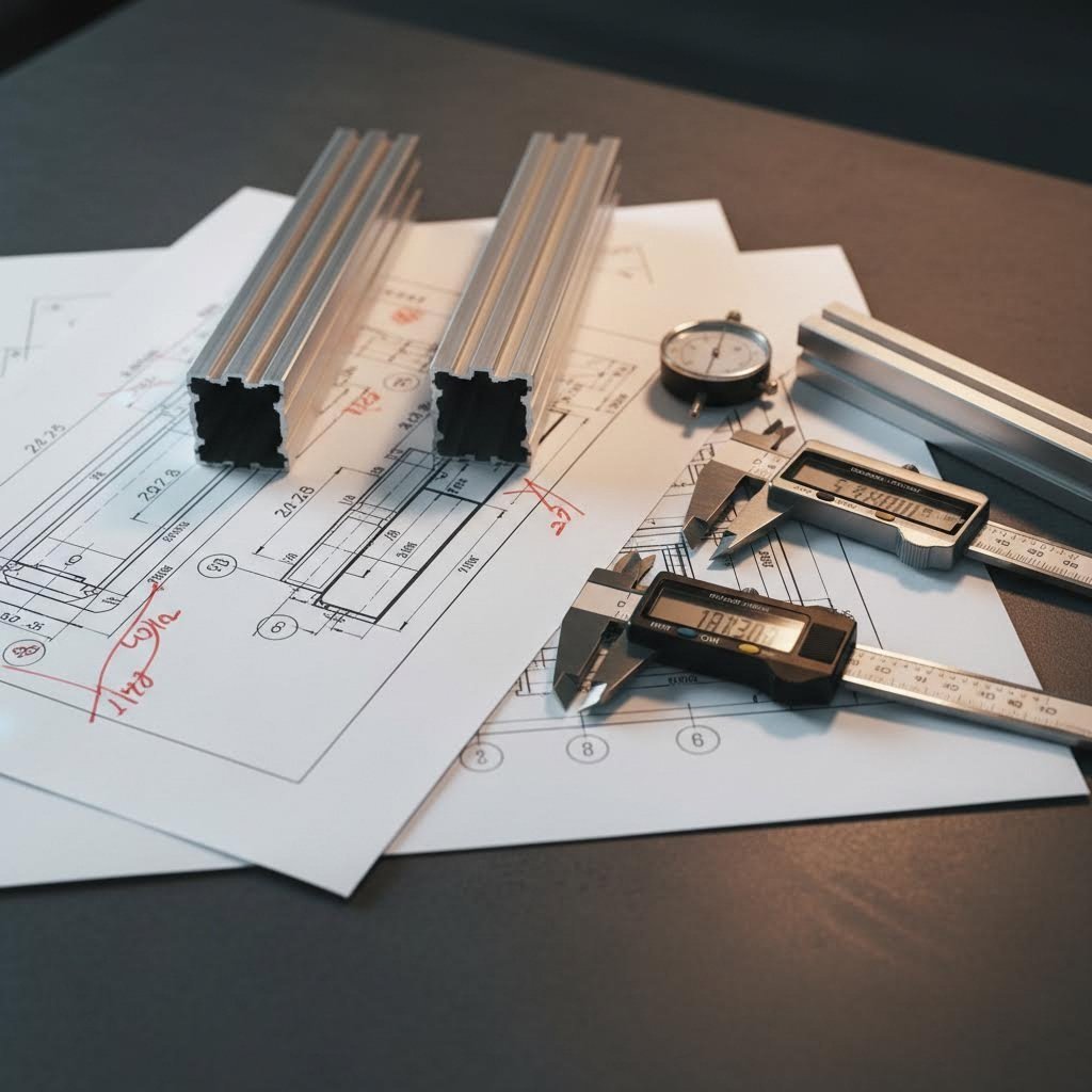
You've selected your alloy, chosen your temper, and designed what seems like a straightforward profile. So why do tolerance-related problems still derail so many extrusion projects? The answer often lies not in manufacturing limitations but in specification errors that occur long before metal meets die. These mistakes cost time, money, and professional credibility—yet they're entirely preventable once you know what to watch for.
According to industry documentation on extrusion design mistakes, common errors include incomplete drawings, failure to share the big picture with manufacturers, and over-specifying tolerances. By understanding these pitfalls and implementing systematic prevention strategies, you'll transform your aluminum extrusion design guidelines from potential problem sources into reliable specification documents.
Here's a scenario that plays out regularly: an engineer specifies ±0.005 inches on every dimension of a profile destined for non-critical framing applications. The result? Costs increase by 50% to 200%, lead times extend, and the project gains zero functional benefit from all that extra precision.
Over-specification represents one of the most expensive mistakes in aluminum extrusion design guidelines. As tolerance specification research confirms, going from a tolerance of ±0.05mm to ±0.01mm can multiply costs by two to five times. Special features like thin walls or complex shapes require extra tooling and setups, further inflating prices.
The root cause? Many designers apply a "tighter is always better" philosophy without evaluating whether tighter tolerances actually improve product function. When reviewing your specifications, ask yourself: what happens if this dimension varies by the standard tolerance amount? If nothing significant changes functionally, you're over-specifying.
Stock aluminum extrusion profiles from catalogs typically meet standard tolerance specifications that work perfectly for most applications. Before requesting custom precision tolerances, check whether stock aluminium extrusion profiles might satisfy your requirements at a fraction of the cost.
Even well-conceived tolerance specifications fail when communication breaks down between designer and manufacturer. Your extruded aluminum shapes catalog or specification sheet is only as useful as your ability to convey what truly matters for your application.
Thermal expansion represents a frequently overlooked communication gap. Aluminum expands at approximately 23 × 10⁻⁶ per degree Celsius. A 10-foot profile experiencing a 20°C temperature swing can change length by nearly 0.055 inches. If your assembly operates in varying temperatures and you haven't discussed this with your supplier, parts that measure perfectly at room temperature may not fit in service conditions.
Critical dimension identification is another common failure point. When every dimension appears equally important on a drawing, suppliers can't prioritize their quality control efforts. The result? Resources spread thin across non-critical features while truly important dimensions receive insufficient attention.
Reading cross-sectional dimension tolerance tables correctly requires attention to several factors. First, determine your profile's circumscribing circle diameter—this determines which tolerance table applies. Next, identify whether each dimension is primarily metal or space. Then locate the row corresponding to your dimension range and read across to find the applicable tolerance. Remember that hollow and semi-hollow profiles often have separate tolerance specifications, particularly for wall thickness and eccentricity.
When documenting tolerance requirements in purchase specifications, clarity prevents disputes. Your aluminum extrusion catalog requests should include: complete dimensional drawings with all tolerances explicitly stated, the applicable industry standard and revision, tolerance class designation for each dimension category, identification of critical dimensions requiring 100% inspection, reference temperature for measurements when thermal expansion matters, and any special requirements for certification or documentation.
The time invested in clear, accurate tolerance specification pays dividends throughout production. Suppliers who understand exactly what you need can quote accurately, plan appropriate quality controls, and deliver profiles that perform as expected. This collaborative approach—built on clear communication and realistic expectations—transforms tolerance specification from a potential problem source into a foundation for successful projects.
You've identified your critical dimensions, selected the right tolerance class, and avoided the common specification mistakes. Now comes the moment of truth: translating all that knowledge into actionable ordering documents that your supplier can execute flawlessly. The gap between understanding aluminum extrusion tolerances and successfully communicating them to manufacturers is where many projects stumble—but it doesn't have to be that way.
Think of tolerance specification as a conversation rather than a one-way transmission. The most successful extrusion projects involve collaborative dialogue between designer and manufacturer, starting well before anyone cuts a die. This section walks you through the complete workflow from initial design considerations through final order placement, ensuring your tolerance requirements translate into parts that perform exactly as intended.
Effective tolerance planning begins the moment you start sketching your profile concept—not after you've finalized drawings and sent them for quoting. According to industry best practices, having discussions with your aluminum extruder during the design and quoting stage is key to mutual tolerance agreement and establishing tolerance hierarchy.
Why does early engagement matter so much? Because tolerances are affected by multiple extrusion factors including press size, billet temperature, extrusion speed, die shape and type, cooling time, amount of post-stretch, and even ambient air temperature. Your supplier understands how these variables interact with your specific geometry—knowledge that's invaluable during design optimization.
Start your design phase tolerance planning by categorizing every dimension into three tiers:
When reviewing aluminum extrusion sizes for your application, consider how dimensional variations stack up in your assembly. A square aluminum extrusion joining four other components accumulates tolerance from each interface. If every part sits at the extreme of its tolerance range, will your assembly still function? This tolerance stack analysis often reveals which dimensions truly require tight control.
For complex assemblies, consider consulting a standard aluminum extrusion profiles pdf from industry sources to understand what's readily achievable before specifying custom requirements. Many applications can use catalog profiles that already meet established tolerance specifications, saving both time and tooling costs.
Clear communication transforms good tolerance planning into successful production. Your supplier needs specific information to quote accurately, design appropriate tooling, and establish effective quality controls. Vague or incomplete specifications lead to misunderstandings, requotes, and potentially non-conforming parts.
Use this comprehensive specification checklist when preparing your order documentation:
The timing of tolerance discussions matters enormously. According to extrusion design guidance, the extrusion conditions required to produce various alloy-temper and profile combinations require close review between customer and producer to determine critical characteristics and tolerance capability. This review should happen during die development—not after production begins.
Why involve your supplier before die cutting? Because die geometry directly determines achievable tolerances. An experienced toolmaker can optimize bearing lengths, adjust metal flow paths, and incorporate features that improve dimensional consistency. These optimizations are straightforward during initial die design but expensive or impossible to retrofit later.
For aluminum t bar extrusion or other profiles with asymmetric features, discuss how die orientation affects tolerance achievement. The position of complex features relative to the die's center influences material flow and dimensional control. Your supplier may recommend design modifications that dramatically improve tolerance capability without compromising functionality.
Sometimes your application demands tolerances that exceed what's achievable through extrusion alone. Rather than abandoning the project or accepting compromised performance, consider how secondary operations can deliver precision where it matters most.
CNC machining represents the most common solution for achieving tight tolerances on specific features. While the base extrusion holds standard tolerances overall, machined surfaces can achieve ±0.001" or better. This hybrid approach—combining extrusion's efficiency for bulk material with machining's precision for critical features—often delivers the best cost-performance balance.
According to manufacturing specifications, saw-cut tolerances can achieve ±0.006" on a case-by-case basis when closer than standard cuts are required. Similarly, surface finishes of 32 RMS are available upon request when standard 63 RMS won't meet your requirements.
Consider secondary operations for:
When planning for secondary operations, communicate the complete manufacturing sequence to your extrusion supplier. They can ensure the base profile provides adequate material stock in machined areas while optimizing other features for as-extruded use. This integrated approach prevents situations where extrusion tolerances interfere with subsequent machining operations.
The goal isn't perfect tolerances everywhere—it's the right tolerances in the right places, achieved through the most cost-effective combination of processes. By planning this workflow from design through ordering, you'll specify aluminum extrusion tolerances that deliver exactly the performance your application demands.
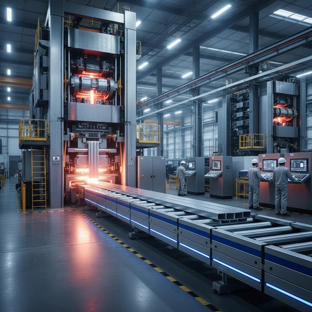
You've mastered the theory of aluminum extrusion tolerances—now how do you translate that knowledge into parts that actually perform in the real world? The answer lies in matching your tolerance requirements to both your application demands and your manufacturing partner's capabilities. Different applications demand fundamentally different tolerance approaches, and understanding these distinctions helps you select suppliers equipped to deliver exactly what your project requires.
Whether you're building with aluminum extrusion for architectural facades or engineering structural aluminium extrusions for industrial machinery, the path to dimensional accuracy runs through experienced manufacturing partners who understand how to control every variable in the extrusion process.
Architectural aluminum extrusions present a unique tolerance challenge: they must be precise enough to ensure proper assembly while maintaining the visual consistency that defines quality construction. Window frames, curtain wall systems, storefront mullions, and aluminum panel extrusions all demand specific combinations of flatness, straightness, and dimensional accuracy.
Consider a typical window frame installation. The aluminum h extrusion forming the frame perimeter must maintain straightness tolerances tight enough that weatherstripping seats properly and glass panels fit without binding. According to flatness tolerance research, acceptable flatness specifications typically define the allowable deviation in millimeters per meter—and even small variations can create visible gaps or sealing failures.
For architectural applications, critical tolerance considerations include:
The challenge intensifies with aluminium extrusion tube components used in railings and handrail systems. These must not only meet dimensional tolerances but also maintain visual alignment across joined sections—any twist or bow becomes immediately apparent to building occupants.
Industrial applications shift the tolerance priority toward dimensional accuracy for assembly fit rather than visual consistency. When aluminium extruded tubes become structural members in conveyor systems, or when complex profiles form machine frames, the critical question becomes: will these parts assemble correctly and function reliably?
Structural aluminium extrusions for industrial machinery face different challenges than their architectural counterparts. According to dimensional accuracy research, ensuring parts fit perfectly into intended assemblies requires controlling not just individual dimensions but also how tolerances stack up across multiple components.
Industrial tolerance priorities typically include:
The difference in approach becomes clear when you compare requirements: an architectural mullion might accept ±0.020" on overall width because it fits into adjustable glazing systems, while an industrial profile serving as a linear bearing rail might demand ±0.005" on the same dimension to ensure smooth carriage travel.
Meeting demanding tolerance requirements—whether for architectural aesthetics or industrial precision—depends heavily on your manufacturing partner's equipment, processes, and quality systems. The gap between acceptable and exceptional tolerance performance often comes down to capabilities that many extruders simply don't possess.
According to advanced extrusion research, maintaining tight tolerances requires sophisticated equipment, precise tooling, and comprehensive process control. Premier extruders leverage CAE simulations, metallurgical expertise, and precision die manufacturing to deliver profiles that consistently meet demanding specifications.
What separates capable manufacturers from the rest? Consider these key capability indicators:
The practical value of these capabilities becomes evident when tolerance challenges arise. When quality control documentation shows that in-process inspection catches dimensional drift before it creates scrap, or when CNC machining delivers ±0.001" on critical mounting surfaces that the base extrusion couldn't achieve alone, you're seeing integrated manufacturing capabilities in action.
How do you evaluate whether a potential manufacturing partner can actually deliver the tolerances your project demands? Look beyond marketing claims to operational realities that directly affect dimensional control.
Start by examining press technology. According to manufacturing capability research, advanced extrusion presses with precise temperature, pressure, and speed control produce more consistent dimensional results than older equipment. Modern presses equipped with real-time monitoring can detect and correct process variations before they affect tolerances.
Evaluate secondary processing capabilities carefully. If your application requires precision features beyond base extrusion capabilities, verify that your supplier offers:
Quality system sophistication matters as much as equipment. Ask about inspection protocols, measurement equipment calibration, and how out-of-tolerance conditions are detected and addressed. Manufacturers with robust quality systems—such as those holding IATF 16949 or similar certifications—demonstrate commitment to dimensional consistency through documented processes and continuous improvement.
Finally, consider communication and technical support. The best tolerance outcomes result from collaborative relationships where your supplier understands not just your dimensional requirements but why those tolerances matter for your application. When manufacturers provide end-to-end support from initial design consultation through production, they can optimize every process step for tolerance achievement rather than treating dimensional control as an afterthought.
By matching your tolerance requirements to manufacturers with appropriate capabilities, equipment, and quality systems, you transform tolerance specifications from hopeful requests into reliable production realities. The result? Aluminum extrusions that meet your dimensional requirements consistently, whether you're creating architectural showpieces or precision industrial components.
Standard aluminum extrusion tolerances follow ANSI H35.2 specifications, typically ranging from ±0.006 inches to ±0.280 inches depending on profile size and complexity. For linear cross-section dimensions, expect ±0.008 inches per inch of dimension. Wall thickness tolerances generally run ±10% of the specified dimension, while twist tolerances allow approximately 0.5 to 1 degree per foot of length. These tolerances work well for most architectural and general industrial applications without requiring premium pricing.
Calculate aluminum extrusion tolerances by first determining your profile's circumscribing circle diameter—the smallest circle enclosing the entire cross-section. Profiles under 10 inches use tighter tolerance tables than larger profiles. Next, identify whether dimensions are 'metal' (75%+ solid) or 'space' (more than 25% open). For straightness, multiply the profile length in feet by 0.0125 inches for sections 0.095 inches thick or greater. Consult Aluminum Association tolerance tables matching your profile type (solid, semi-hollow, or hollow) for precise values.
Standard tolerances represent what competent extruders achieve using normal production processes, typically ±0.020 to ±0.030 inches depending on profile size. Precision tolerances demand significantly tighter control—sometimes as precise as ±0.005 to ±0.006 inches—requiring specialized equipment, slower extrusion speeds, and enhanced inspection. Precision tolerances can increase costs by 50% to 200% and are reserved for aerospace components, electronic enclosures, and critical-fit assemblies where dimensional variation creates functional problems.
Alloy selection significantly impacts achievable tolerances. Softer alloys like 6063 flow more uniformly through intricate die geometries, achieving tighter tolerances on complex shapes. Harder alloys like 6061 require higher extrusion pressure and may need design adjustments for equivalent precision. Temper also matters—T5 profiles maintain better dimensional stability than T6 because T6's separate solution heat treatment and quenching can cause warping, especially on asymmetric profiles requiring additional straightening operations.
Multiple factors influence dimensional accuracy: profile complexity (solid profiles achieve tighter tolerances than hollow), circumscribing circle diameter (larger profiles permit wider tolerances), wall thickness variations, alloy properties, temper designation, and extrusion process parameters including press size, billet temperature, extrusion speed, and cooling methods. Die design quality, post-extrusion stretching, and ambient temperature during measurement also affect final dimensions. Working with experienced manufacturers like Shengxin Aluminium who control these variables through advanced equipment and quality systems ensures consistent tolerance achievement.



 Інтернет-сервіс
 0086 136 3563 2360
 sales@sxalu.com
 +86 136 3563 2360
 Українська
 English
 français
 Deutsch
 русский
 español
 português
 العربية
 ไทย
 Việt