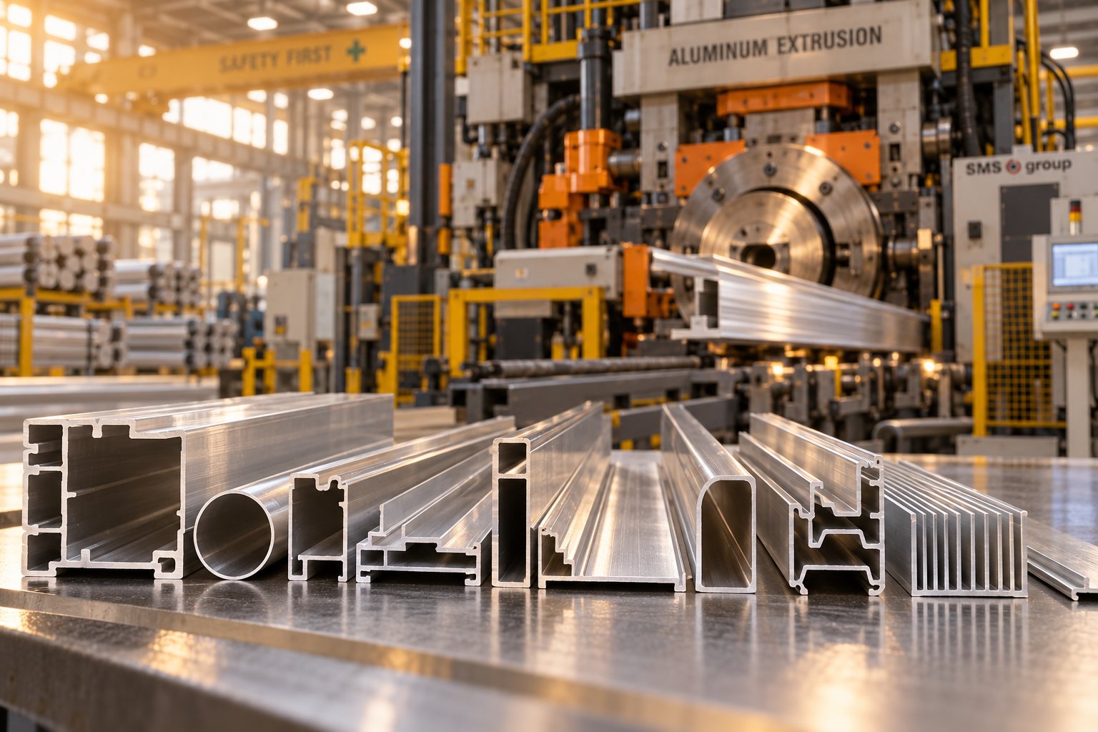
When you're designing a product that relies on aluminum extrusion, one specification can make or break your entire project: wall thickness. But here's what most suppliers won't tell you upfront—there's a significant difference between what's technically possible and what's actually manufacturable at scale. Understanding this distinction could save you months of development time and thousands of dollars in tooling costs.
Minimum wall thickness in aluminum extrusion refers to the thinnest cross-sectional dimension of material that can be reliably produced while maintaining both structural integrity and consistent production quality. Think of it as the floor—the absolute lowest you can go without compromising the extrusion process or the finished part's performance.
For engineers and designers, this specification directly influences everything from weight reduction goals to material costs. Procurement professionals need to understand these limits because specifying walls that are too thin can lead to rejected quotes, increased scrap rates, or suppliers padding their estimates to account for production risks.
The aluminum extrusion process forces heated aluminum billets through shaped dies under tremendous pressure. As the material flows through increasingly narrow passages, physical limitations emerge. According to industry reference charts from Bonnell Aluminum, minimum practical wall thicknesses range from 0.040 inches for small solid profiles up to 0.236 inches for larger hollow shapes—depending on the profile's circumscribing circle size.
You might wonder why this matters if you're not pushing extreme limits. Here's the reality: aluminum extrusion dimensions and tolerances are interconnected. Thinner walls mean tighter tolerance windows become exponentially harder to achieve. A real-world example illustrates this perfectly—a German LED lighting manufacturer requested thin wall extrusions at 0.7mm with tolerances of ±0.03mm on critical dimensions. After technical evaluation, the manufacturer could only achieve ±0.3mm on certain features, a tenfold difference from the original specification.
The gap between theoretical minimums and production-stable minimums is where most projects encounter unexpected delays. A wall thickness that's technically achievable in a lab setting may result in 30-40% higher scrap rates during mass production.
When reviewing any aluminum extrusion design guide, you'll find general thickness recommendations. However, these guidelines rarely distinguish between what's possible on a prototype run versus what's economically viable for production volumes. This oversight leads to frustrating back-and-forth between design teams and manufacturers.
Understanding aluminum extrusion tolerances in relation to wall thickness helps you make smarter design decisions. The thinner you go, the more flexibility the profile exhibits—which directly impacts dimensional consistency. For various alum extrusion shapes, this relationship between thickness and stability becomes even more critical when assembly with other components is required.
In the following sections, we'll dive deeper into the technical factors that determine these limits, compare capabilities across different alloys, and provide actionable guidance for specifying wall thicknesses that balance performance requirements with manufacturing reality.
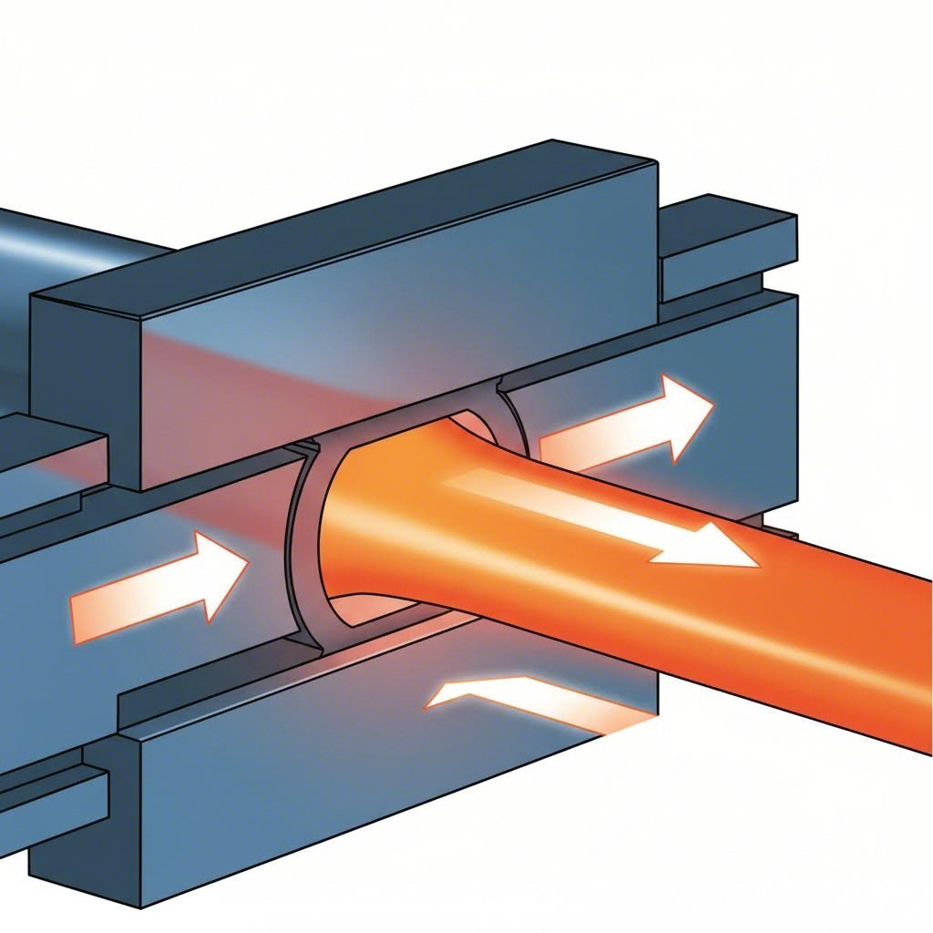
Ever wondered why your supplier quoted a 1.2mm minimum wall when you've seen competitors achieve 0.8mm? The answer lies not in secrecy, but in the complex physics happening inside the extrusion press. Understanding these metallurgical and mechanical factors gives you leverage in design discussions and helps you identify which manufacturers can genuinely deliver thinner walls versus those making optimistic promises.
Picture heated aluminum flowing through an aluminum extrusion die like thick honey being pushed through a stencil. As the material encounters narrower passages, physics imposes hard limits on what's achievable. The narrower the gap, the more resistance the aluminum encounters—and resistance creates problems.
During extrusion aluminum behaves as a viscoplastic material, meaning its flow characteristics depend on both temperature and the rate at which force is applied. When material must flow through thin wall sections, friction against die surfaces increases dramatically. This friction generates localized heat that can cause surface defects, dimensional instability, or even tearing of the profile wall.
Research from the Aluminum Extruders Council confirms that achieving high extrusion ratios—the measure of how much the billet cross-section is reduced—requires substantial force to overcome immense friction and deformation resistance. Thin wall sections demand the highest extrusion ratios, pushing equipment to its limits.
The relationship between extrusion speed and wall integrity creates a delicate balancing act. According to production data from aluminum formwork manufacturers, extrusion speeds typically range between 5m/min and 12m/min for complex profiles. Push too fast through thin wall sections, and you risk:
Slow the process to improve quality, and you encounter different issues. Extended contact time between aluminum and die surfaces increases heat transfer, potentially pushing temperatures beyond optimal ranges. For aluminum extruded profiles with thin walls, this thermal management challenge becomes even more pronounced because thin sections cool faster than thick ones, creating internal stresses.
Here's something most aluminum extrusion design guides underemphasize: your supplier's equipment determines their thin wall capabilities as much as their technical expertise. Press tonnage—the maximum force the extrusion press can apply—directly correlates with achievable minimum thicknesses.
Think of press tonnage as the engine in a vehicle. A compact car might technically climb a steep mountain road, but an underpowered engine will struggle, overheat, and potentially fail. Similarly, smaller extrusion presses face physical limitations when attempting thin wall profiles.
Larger presses in the 3000T to 5500T range unlock capabilities that smaller equipment simply cannot match:
Production experience with 4500T equipment demonstrates this principle clearly. When extruding large formwork profiles through 368mm diameter containers, adequate tonnage enables wall thickness control within ±0.2mm tolerance—a specification that would be nearly impossible on significantly smaller presses.
The metallurgical factors limiting minimum wall thickness extend beyond equipment considerations. Several material-level constraints determine how thin you can reliably go:
Understanding these technical realities transforms your conversations with extrusion suppliers. Instead of accepting blanket minimum thickness specifications, you can ask informed questions about press capabilities, billet quality protocols, and temperature management practices. This knowledge becomes especially valuable when comparing capabilities across different alloy types—a topic that reveals even greater variation in achievable wall thicknesses.
You've selected the perfect profile geometry and found a supplier with impressive press capabilities. But here's a variable that can override all your careful planning: alloy selection. The aluminum extrusion alloys you specify dramatically influence how thin your walls can realistically go—and this relationship is rarely explained in detail by suppliers.
Why does this matter so much? Each alloy in the 6000 and 7000 series responds differently when heated and forced through an extrusion die. Some flow like warm butter, filling intricate thin-wall sections with ease. Others resist deformation stubbornly, requiring thicker walls to maintain production stability. Understanding these differences helps you make smarter trade-offs between strength requirements and manufacturing feasibility.
The relationship between alloy properties and achievable wall thickness comes down to one fundamental concept: extrudability. This term describes how easily an alloy flows through die openings under pressure. According to Alexandria Industries, every step up the mechanical properties ladder causes a corresponding loss in extrudability—and parallel to that, it also has a negative impact on achievable minimum wall thickness.
Think of extrudability as inversely proportional to strength. The same characteristics that make an alloy stronger—higher magnesium content, added copper, increased silicon—also make the material more resistant to deformation. This resistance means more force is required to push material through thin passages, and more things can go wrong during that process.
For aluminum profiles extrusion projects requiring thin walls, alloy selection becomes a critical early decision. Here's what you need to understand about the major aluminum extrusion alloys:
6063 Alloy: This is the gold standard for thin-wall extrusions. With lower magnesium and silicon content compared to its stronger cousins, 6063 flows smoothly through complex die geometries. Production data confirms that 6063 can achieve wall thicknesses down to 0.025 inches (0.64mm) on suitable profiles. Its excellent surface finish characteristics make it ideal for architectural aluminum extrusion applications where aesthetics matter alongside dimensional precision.
6060 Alloy: A close relative of 6063 with somewhat lower mechanical properties, 6060 allows for even more intricate aluminum extrusion profiles. According to industry data from Yajia Aluminum, this alloy excels in heat sink profiles where complex thin-fin geometries require maximum material flow.
6005 Alloy: When you need a step up in strength without sacrificing too much extrudability, 6005 offers a middle ground. This medium-strength structural alloy works well for load-bearing aluminium extrusion types but requires slightly thicker walls than 6063 to maintain production consistency.
6061 Alloy: Here's where limitations become significant. The copper content in 6061 enhances machinability and strength but creates greater resistance during extrusion. Industry references confirm minimum wall thicknesses of 0.035 to 0.040 inches (0.89-1.02mm) for 6061—roughly 40-60% thicker than what's achievable with 6063.
7075 Alloy: This aerospace-grade alloy sits at the extreme end of the strength spectrum but comes with severe extrudability limitations. The high zinc content that provides exceptional strength makes 7075 one of the most difficult alloys to extrude. Minimum wall thicknesses typically exceed 0.050 inches (1.27mm), and complex profile geometries may be impossible altogether.
The 6063 versus 6061 decision represents the most common trade-off engineers face when specifying aluminum extrusion applications. Understanding exactly why these alloys differ helps you justify your choices to stakeholders and set realistic expectations with suppliers.
Let's examine the mechanical properties driving this difference. According to comparative data from industry sources, 6061-T6 delivers approximately 276 MPa yield strength and 310 MPa tensile strength, while 6063-T6 provides around 240 MPa yield strength and 270 MPa tensile strength. That 15% strength advantage comes at a cost—significantly reduced extrudability and thicker minimum walls.
Why does higher yield strength translate to thicker wall requirements? When aluminum is forced through thin die openings, it must deform plastically. Higher yield strength means the material resists this deformation more aggressively. The extrusion press must work harder, friction increases, and the risk of incomplete die filling, surface defects, or wall tearing multiplies.
Imagine you're specifying a structural frame component for outdoor signage. You need adequate strength to withstand wind loads, but weight and material cost matter too. With 6063, you might achieve a 1.0mm wall thickness reliably. The same profile in 6061 would require 1.4mm walls minimum—a 40% increase in material content. However, 6061's higher strength might let you use a smaller overall profile, potentially offsetting the wall thickness penalty.
The table below provides a comprehensive comparison to guide your aluminum extrusion profiles selection:
| Alloy Type | Typical Minimum Wall Thickness | Extrudability Rating | Yield Strength (T6) | Best Applications |
|---|---|---|---|---|
| 6063 | 0.025" (0.64mm) | Excellent | ~240 MPa | Architectural profiles, window frames, decorative trim, heat sinks |
| 6060 | 0.025" (0.64mm) | Excellent | ~200 MPa | Complex heat sinks, intricate decorative profiles |
| 6463 | 0.030" (0.76mm) | Very Good | ~220 MPa | Bright anodized trim, polished decorative components |
| 6005/6005A | 0.030" (0.76mm) | Good | ~260 MPa | Structural extrusions, ladder rails, modular frames |
| 6061 | 0.035-0.040" (0.89-1.02mm) | Moderate | ~276 MPa | Structural components, automotive frames, CNC machined parts |
| 6082 | 0.045" (1.14mm) | Difficult | ~340 MPa | Heavy structural applications, marine environments, steel replacement |
| 7075 | 0.050"+ (1.27mm+) | Very Difficult | ~503 MPa | Aerospace fittings, high-stress components, specialized equipment |
Notice the pattern: as you move from 6063 toward 7075, minimum wall thickness requirements increase in step with mechanical properties. This isn't arbitrary—it reflects fundamental material science principles that no amount of supplier expertise can completely overcome.
The practical implication for your projects? Always start your design exploration with 6063 if thin walls are a priority. Only move to stronger alloys when structural analysis proves 6063 cannot meet load requirements. When you do need 6061 or harder alloys, design your profile geometry to accommodate thicker walls from the beginning rather than trying to force thin-wall specifications that will cause production headaches.
With alloy selection principles established, the next critical variable enters the picture: profile geometry itself. Whether you're designing solid or hollow shapes introduces an entirely different set of wall thickness constraints that further refine what's achievable.
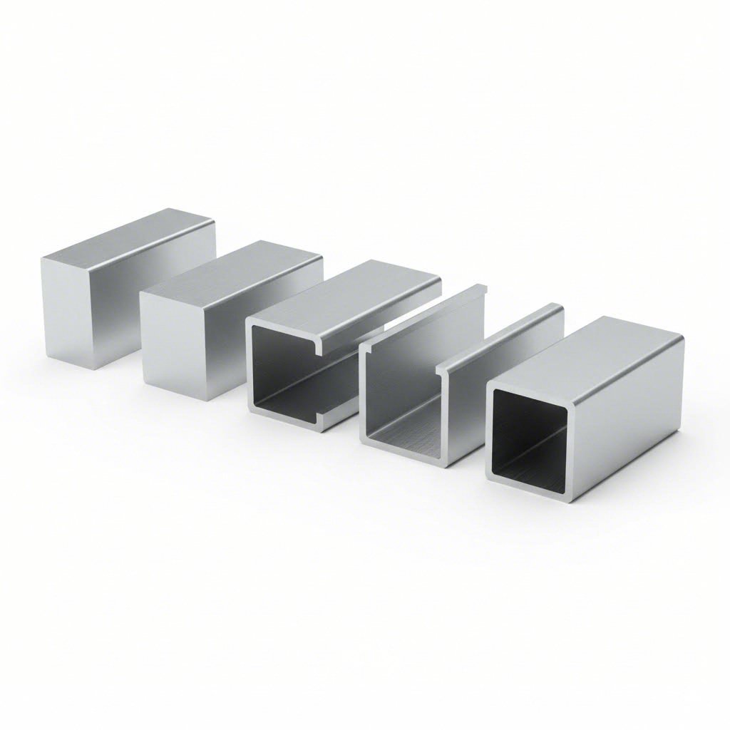
Here's a question that trips up even experienced engineers: why can your supplier achieve 0.040" walls on a solid angle profile but insists on 0.078" for a similarly-sized rectangular tube? The answer reveals one of the most overlooked aspects of aluminum extrusion minimum wall thickness specifications—the fundamental difference between solid and hollow profile manufacturing.
Understanding this distinction isn't just academic. It directly impacts your material costs, weight targets, and design flexibility. When you grasp why hollow extruded aluminum profiles face stricter thickness requirements, you gain negotiating power with suppliers and make smarter design decisions from the start.
Solid aluminum extrusion shapes represent the simplest manufacturing scenario. Without internal voids, material flows through the die in a relatively straightforward manner. The aluminum doesn't need to split, flow around obstacles, and rejoin—it simply pushes through the shaped opening.
This simplicity translates directly into thinner achievable walls. According to reference data from Bonnell Aluminum's design guidelines, solid profiles and semihollows can achieve minimum wall thicknesses starting at 0.040" for circumscribing circles under 2 inches. Compare this to Class 2 hollow shapes in the same size range, which require 0.055" minimum—nearly 40% thicker.
What makes solid dies more forgiving? Several factors work in your favor:
For designers specifying extruded aluminum sections, solid profiles offer maximum flexibility when thin walls are a priority. A C-channel, angle, or flat bar can push closer to theoretical minimums than any hollow alternative. However, the structural efficiency of hollow shapes often outweighs this wall thickness advantage—which is exactly why understanding hollow profile limitations becomes essential.
Hollow profiles introduce a manufacturing complexity that fundamentally changes the wall thickness equation. When you specify a tube, enclosed channel, or any shape with internal voids, you're asking the extrusion process to perform a remarkable feat: split the aluminum flow, direct it around internal supports, and weld it back together seamlessly—all while maintaining dimensional precision in thin wall sections.
The die construction required for hollow shapes explains why thicker walls become necessary. As detailed in the Aluminum Extrusion Manual, hollow dies consist of two primary components: a mandrel that creates the internal void and a die cap that forms the external profile. The mandrel sits on legs or webs called bridges, and aluminum must flow around these bridges before reuniting in the weld chamber.
This flow-split-rejoin sequence creates specific challenges for thin walls:
The industry classifies hollow shapes into three categories based on complexity, each with different wall thickness implications:
Class 1 Hollow Shapes: These are the simplest hollows—round voids of 1 inch or larger diameter, symmetrically balanced around the void by two or more axes. Think standard round tubes. Their symmetry allows for the most uniform material flow and the thinnest relative walls among hollow profiles.
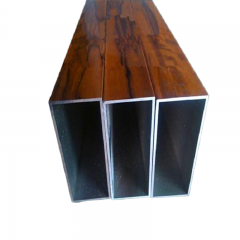
Class 2 Hollow Shapes: This category covers shapes that aren't Class 1 but have a single void no smaller than 0.375 inches in diameter (or 0.110 square inches in area) and fit within a 5-inch circumscribing circle. Rectangular tubes and simple enclosed channels typically fall here. Wall thickness requirements increase compared to Class 1 due to asymmetric flow patterns.
Class 3 Hollow Shapes: Any hollow that doesn't qualify as Class 1 or 2 lands here—including multi-void profiles, complex asymmetric sections, and larger enclosed shapes. These require the thickest walls and most careful die design to produce reliably.
Sounds complex? Here's the key relationship that simplifies everything: circumscribing circle diameter (CCD) directly correlates with minimum achievable wall thickness. The CCD is simply the diameter of the smallest circle that completely encloses your profile's cross-section. Larger circles mean thicker minimum walls—regardless of whether your profile is solid or hollow.
Why does size matter so much? Larger profiles require larger dies, longer material flow paths, and greater forces to extrude. Thin walls in large profiles experience proportionally greater stress during production. According to Bonnell Aluminum's reference charts, a hollow profile with a 4-5 inch CCD requires 0.094" minimum walls—more than double the 0.040" achievable for a solid profile under 2 inches.
The following table compares minimum wall thickness requirements across profile types and sizes, giving you a practical reference for design decisions:
| Circumscribing Circle (inches) | Solid & Semihollow Minimum | Class 2 Hollow Minimum | Complexity Factor |
|---|---|---|---|
| 0.5 to under 2 | 0.040" | 0.055" | +38% for hollow |
| 2 to under 3 | 0.045" | 0.062" | +38% for hollow |
| 3 to under 4 | 0.050" | 0.078" | +56% for hollow |
| 4 to under 5 | 0.062" | 0.094" | +52% for hollow |
| 5 to under 6 | 0.078" | 0.110" | +41% for hollow |
| 6 to under 7 | 0.094" | 0.125" | +33% for hollow |
| 7 to under 8 | 0.110" | 0.140" | +27% for hollow |
| 8 to under 9 | 0.125" | 0.156" | +25% for hollow |
| 9 to under 10 | 0.140" | 0.188" | +34% for hollow |
| 10 to under 12 | 0.156-0.172" | 0.204-0.220" | +28-31% for hollow |
Notice that the percentage difference between solid and hollow minimums varies across sizes—it's not a fixed ratio. This reflects the complex interplay between die geometry, material flow dynamics, and thermal management at different scales.
For practical design work, imagine you're specifying extruded shapes for a modular framing system. You need both solid corner brackets (simple L-angles) and hollow rectangular tubes for the main frame members. If your tube has a 3-inch CCD, you're looking at 0.078" minimum walls for the hollow sections versus 0.050" for similarly-sized solid brackets. That 56% thickness difference translates directly to weight and material cost variations you'll need to account for in your project economics.
The semihollow classification adds another layer to consider. A semihollow partially encloses a void—think of a C-channel with a narrow gap. Whether a profile qualifies as semihollow versus solid depends on the gap ratio calculation: the area of the partially-enclosed void divided by the square of the gap width. When this ratio exceeds threshold values published in industry standards, the shape transitions from solid to semihollow classification, with corresponding adjustments to achievable minimum thicknesses.
With profile geometry constraints now clear, the next crucial factor comes into focus: the die itself. How die designers engineer their tooling for thin-wall production reveals why some suppliers can reliably achieve specifications that others consider impossible.
You've selected the right alloy, chosen between solid and hollow geometries, and confirmed your supplier has adequate press tonnage. But here's the factor that often determines whether your thin wall specification succeeds or fails: die design. The tooling that shapes your extruded profile is where theoretical minimums meet manufacturing reality—and where experienced die designers separate achievable specifications from wishful thinking.
Why does die design matter so much for thin walls? When aluminum flows through increasingly narrow passages, every aspect of die geometry influences whether material fills completely, flows uniformly, and exits with consistent dimensions. A well-engineered die can push wall thickness closer to theoretical limits; a poorly designed one creates scrap, surface defects, and dimensional headaches that no amount of process adjustment can fix.
Imagine the extrusion die as a precision instrument rather than a simple shaping tool. For thin wall production, every geometric feature must work in harmony to control material flow, manage pressure distribution, and minimize stress concentrations that cause premature wear or profile distortion.
According to research published by ScienceDirect, die design for thin-walled profiles focuses on reducing localized stress, increasing weld quality, reducing die deflection under extrusion pressure, and achieving uniform exit velocity across the entire profile cross-section. These four objectives often compete with each other, requiring careful optimization.
The bearing length—the parallel section of the die opening where final shaping occurs—plays a critical role in thin wall capability. As noted in aluminum extrusion design guidelines from DGMF Mold Clamps, thinner wall sections typically require shorter bearing lengths to reduce friction and flow resistance. The general principle: "the thinner the wall thickness somewhere in the profile, the greater the perimeter, the more complicated the shape, and the farther away from the center of the extrusion barrel, the shorter the sizing zone."
However, bearing length isn't a simple "shorter is better" equation. Too short, and material exits before achieving proper dimensional stability. Die designers must balance flow equalization against surface quality—a trade-off that becomes increasingly delicate as walls thin.
Pocket design represents another critical variable. Pockets are relief areas machined into the die face that pre-direct material flow before it enters the bearing. For thin wall sections, properly sized pockets reduce the sudden pressure changes that cause flow instability. Research confirms that relatively large feeders and high welding chambers improve both strength and deformability of thin-walled profiles.
The following factors enable thinner walls when properly engineered:
For thin-walled hollow profiles, mandrel design becomes especially critical. According to production studies, the mandrel tooth—the component that creates internal voids—operates in extreme conditions at high temperatures and pressures. Each tooth functions as a slender cantilever structure that can deform or even fracture, directly influencing dimensional accuracy and die service life. Statistics confirm that mandrel failure is the predominant cause of die issues when producing thin-walled multi-port tubes.
When does a profile cross the line from solid to semihollow? The gap ratio calculation answers this question and directly impacts your minimum wall thickness specifications.
The gap ratio formula examines partially enclosed voids—spaces that are almost but not completely surrounded by profile material. Think of a C-channel where the opening is narrow relative to the enclosed area. The calculation divides the area of the partially enclosed void by the square of the gap width. When this ratio exceeds published thresholds (typically around 1:3 or 1:4 depending on profile size), the shape transitions from solid to semihollow classification.
Why does this matter for wall thickness? Semihollow profiles require different die construction than true solid shapes. The narrow gap creates a "tongue" in the die that must withstand significant bending forces during extrusion. According to industry standards, "the tongue die and plane split die need to check the shear, bending, and compressive strength, and the tongue and needle tip also need to consider the tensile strength." Thinner walls amplify these stresses, potentially limiting achievable minimums.
For practical application, consider an extruded profile with a partially enclosed channel. If the void area measures 0.5 square inches and the gap width is 0.25 inches, your gap ratio is 0.5 ÷ (0.25)² = 8. This high ratio clearly indicates semihollow classification, meaning you'll face tighter wall thickness constraints than a fully open channel of similar size.
Die designers use gap ratio calculations to determine tongue thickness requirements. When walls need to be thin but the gap ratio pushes toward semihollow territory, widening the gap opening slightly might allow solid-die construction with its corresponding thinner wall capability. This design flexibility often represents the difference between a manufacturable specification and an impractical one.
Die wear introduces time-dependent variations that particularly affect thin wall consistency. As extrusion runs accumulate, bearing surfaces erode, pocket geometries shift, and the precise dimensional relationships that enable thin walls gradually degrade. According to die design research, this wear pattern affects thin sections disproportionately—the same absolute wear that barely registers on a 3mm wall might represent 10-15% of a 0.8mm wall's thickness.
For production runs requiring thin walls, monitoring die condition becomes essential. First-article inspection might confirm perfect dimensions, but maintaining that precision through thousands of meters of extrusion requires understanding wear patterns and planning appropriate die maintenance intervals. Experienced manufacturers track dimensional trends and schedule die refurbishment before thin wall specifications drift out of tolerance.
With die design principles established, another crucial consideration emerges: how do production conditions affect whether your carefully-specified thin walls actually remain consistent throughout manufacturing? The stability factors that separate reliable thin-wall production from problematic runs deserve careful examination.

Your die is perfectly designed, your alloy selected, and your profile geometry optimized. But here's what separates a specification that looks good on paper from one that performs consistently in production: stability factors. These are the manufacturing variables that determine whether your thin wall extrusion comes off the press with predictable quality—or creates headaches with every production run.
Understanding production stability isn't just academic. When suppliers classify a thin wall specification as "stable" versus "challenging," they're signaling significant differences in expected scrap rates, lead times, and pricing. Knowing what drives these classifications gives you leverage to specify smarter and negotiate better.
Think of thin wall extrusion as a balancing act where multiple variables must stay within narrow ranges simultaneously. When producing standard aluminum extrusions with typical wall thicknesses, the process tolerates some variation. Push walls thinner, and that tolerance window shrinks dramatically.
Temperature control sits at the center of production stability. According to research from the Norwegian University of Science and Technology, thin-walled extrusions show severe dimensional variations including gap opening, sidewall inclination, and local convexity—defects directly tied to thermal management during and after extrusion. The billet must enter the press at precisely controlled temperatures, typically between 460°C and 490°C depending on alloy. Too hot, and material flows too freely, creating inconsistent wall thickness. Too cold, and increased resistance causes incomplete die filling or surface tearing.
Extrusion speed compounds these thermal challenges. Faster speeds generate more friction heat, pushing temperatures upward during the press cycle. For precision aluminum products with thin walls, operators must continuously balance productivity against quality. Standard extruded aluminum sizes might run at 15-20 meters per minute, but thin wall profiles often require speeds of 5-12 meters per minute to maintain dimensional consistency.
The following factors determine whether a thin wall specification receives a "stable" or "challenging" production rating:
For specialized shapes like oval aluminum extrusion profiles, these stability factors become even more critical. Non-symmetric cross-sections experience differential cooling that can pull thin wall sections out of tolerance after the profile exits the die.
Here's something most suppliers won't emphasize during quoting: the extrusion press is only the beginning. Post-extrusion processes—stretching, aging, and finishing—can make or break your thin wall dimensional requirements. Understanding these downstream effects helps you specify tolerances that remain achievable through the entire manufacturing chain.
Stretching represents the first major post-extrusion operation. As profiles exit the press, they're gripped and pulled to straighten twist and bow while relieving internal stresses. Research published in Metals journal demonstrates that a novel stretch-based correction method achieved 92% improvement in dimensional accuracy for thin-walled U-channel profiles—but also revealed that springback after stretching creates new dimensional challenges that thin walls cannot resist as effectively as thicker sections.
The stretching force itself poses risks for thin walls. Standard aluminium extrusions with adequate wall thickness absorb stretching loads without permanent distortion. But thin-walled profiles, especially those with asymmetric cross-sections, may experience localized yielding that shifts critical dimensions. According to the same research, "the profile sidewall is mainly subject to a pure bending state, while the profile bottom is under pure bending in the inserting stage and changes to the stretching stress state in the calibration stage." This stress distribution affects how thin sections respond to correction forces.
Aging—the heat treatment that develops final mechanical properties—introduces additional thermal cycles that thin walls must survive without warping. The T5 and T6 tempers common in extruded aluminum sizes require heating profiles to 160°C-190°C for several hours. Thin walls heat and cool faster than thick sections in the same profile, potentially creating internal stresses that manifest as dimensional deviation after treatment.
Surface finishing adds the final layer of complexity. Whether your specification calls for anodizing, powder coating, or mechanical finishing, each process applies forces or temperatures that thin walls must withstand. Anodizing builds an oxide layer that effectively thickens walls slightly—a consideration when tolerances are tight. Powder coating requires oven curing at 180°C-200°C, another thermal cycle that challenges dimensional stability.
Tolerance specifications interact directly with achievable minimum wall thickness. Tighter tolerances require more stable production conditions, which in turn demand thicker walls as a buffer against variation. According to Bonnell Aluminum's design guidance, the Aluminum Association publishes standard tolerance charts, but thin wall profiles often cannot meet these standards without specification adjustments.
A practical example illustrates this relationship: a profile with 1.0mm nominal wall thickness and ±0.1mm tolerance allows 10% variation. The same ±0.1mm tolerance on a 0.6mm wall represents nearly 17% variation—far more challenging to maintain consistently. Suppliers may quote the thinner wall but require relaxed tolerances to compensate for inherent process variation.
The economics of thin wall production connect directly to these stability factors. Every parameter that moves from "stable" toward "challenging" increases expected scrap rates, extends lead times, and ultimately affects your project costs—the subject that deserves its own careful examination.
Here's the conversation suppliers often avoid during initial quoting: how does your wall thickness specification actually affect project economics? While thinner walls promise material savings and weight reduction, the manufacturing reality introduces cost variables that can quickly offset those benefits. Understanding these trade-offs helps you specify wall thicknesses that optimize total project value—not just material costs.
When you push toward minimum wall thicknesses, several cost drivers shift in ways that aren't immediately obvious. According to American Douglas Metals, raw material expenses constitute approximately 90% of basic extrusion costs. This means thinner walls should deliver proportional savings, right? Not quite—the manufacturing complexity introduced by thin specifications often erodes those material savings.
Die costs represent the first budget impact. While aluminum extrusion tooling remains economical compared to alternatives—custom dies often cost under $1,000 versus $30,000+ for casting tools—thin wall specifications demand more sophisticated die engineering. Complex die geometries with optimized bearing lengths, flow-promoting pockets, and precision-ground surfaces require additional design time and machining operations. For aggressive thin wall targets, die costs can increase 30-50% over standard specifications.
Production speed directly affects per-piece economics. Standard aluminum extrusions might run at 15-20 meters per minute, but thin wall profiles often require speeds of 5-12 meters per minute to maintain quality. This 40-60% speed reduction translates almost directly to increased labor and equipment costs per kilogram of finished product. When you extrude aluminum at slower rates, fixed costs spread across fewer parts.
Scrap rates compound these speed penalties. Thin wall profiles operate with tighter process windows—any temperature deviation, speed fluctuation, or billet inconsistency can push dimensions out of tolerance. Industry experience suggests scrap rates for challenging thin wall specifications can reach 15-25% compared to 3-5% for standard wall thicknesses. Every scrapped meter represents lost material, energy, and labor.
The following cost factors shift when specifying thinner walls:
Smart specification starts with understanding what wall thickness actually delivers for your application. According to design-for-manufacturability principles outlined by TrustBridge, designers often overestimate how tight specifications must be. Overly aggressive thin wall targets force slower production, increased inspection, more rejects, and ultimately higher costs.
Consider the total cost picture before finalizing specifications. A 10% reduction in wall thickness might save 10% on material costs—but if it doubles your scrap rate and cuts production speed by 40%, your per-piece cost actually increases. The breakeven analysis depends on your specific volumes, quality requirements, and supplier capabilities.
Volume plays a critical role in this equation. Mass production effectively dilutes fixed costs including die manufacturing and equipment setup. For high-volume aluminum extrusions, investing in optimized thin wall dies makes economic sense because tooling costs amortize across thousands of units. Small batch production offers greater flexibility but incurs higher per-unit costs, making standard wall thicknesses more economical.
Design-for-manufacturability offers a practical framework for balancing performance against cost. Rather than specifying the absolute minimum wall thickness your application can tolerate, ask: what wall thickness optimizes total delivered value? Sometimes adding 0.2mm to your wall specification eliminates production challenges that would otherwise increase costs by 20-30%.
Strategic design choices can recover thin wall benefits without manufacturing penalties. According to the Aluminum Extruders Council, aluminum's tooling economics favor extrusion over alternatives—simple shapes cost only a few hundred dollars in tooling versus thousands for injection molding or casting. Use this flexibility to your advantage: instead of fighting for marginal wall thickness reductions, consider profile geometry optimizations that achieve similar weight or cost targets with manufacturable wall specifications.
The most cost-effective approach often involves early supplier collaboration. Experienced manufacturers can identify which wall thickness targets fall within stable production windows versus those that require premium pricing to account for yield risks. This transparency—when you can achieve it—allows specification decisions that balance engineering requirements against real-world manufacturing economics. The application-specific guidelines that follow will help you calibrate these decisions for your particular industry context.
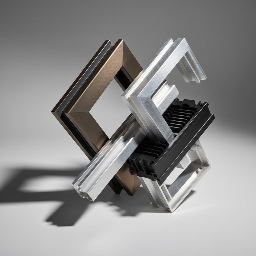
You've mastered the technical fundamentals—alloy selection, profile geometry, die design, and cost trade-offs. But how does all this knowledge translate into real-world decisions for your specific project? The answer depends heavily on your application. A window frame engineer faces entirely different wall thickness constraints than an automotive thermal management designer, even when both specify aluminum profile extrusion for their components.
Understanding application-specific requirements helps you specify wall thicknesses that satisfy structural, thermal, and aesthetic demands without over-engineering—or creating manufacturing headaches. Let's examine how different industries approach minimum wall thickness decisions and what drives their varying requirements.
Architectural applications represent the largest single market for extruded aluminum profile products, and they showcase the full spectrum of wall thickness considerations. Building with aluminum extrusion means balancing structural performance, weather resistance, aesthetic appeal, and regulatory compliance—all while meeting cost targets that competitive bidding demands.
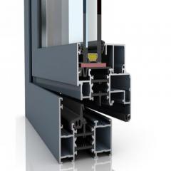
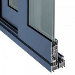
Window and door frames typically specify wall thicknesses between 1.2mm and 2.0mm for primary structural members. Why this range? These profiles must resist wind loads, support glass weight, accommodate thermal expansion, and maintain weatherseal compression over decades of service. According to architectural standards, profiles thinner than 1.2mm struggle to maintain the dimensional stability required for reliable weathersealing, while thicknesses beyond 2.0mm add material cost without proportional performance benefit.
Curtain wall systems push into thicker territory—often 2.0mm to 3.0mm for main mullions and transoms. These profiles span greater distances between anchor points and must resist substantial wind pressures on high-rise buildings. The structural calculations driving these specifications account for deflection limits (typically L/175 to L/240 of span length) that thinner walls cannot meet without excessive profile depth.
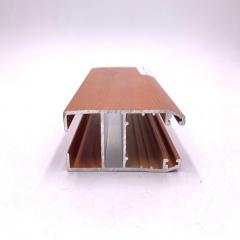
Decorative trim and accent profiles represent the opposite extreme. When profiles serve purely aesthetic functions—fascia covers, decorative reveals, or interior trim—wall thicknesses can drop toward manufacturing minimums. A 15mm aluminum extrusion used as decorative cladding might specify 0.8mm walls where structural loads are negligible and the profile receives full backing support from substrate materials.
Thermal performance introduces additional wall thickness considerations for architectural applications. Thermally broken profiles—where insulating polyamide strips separate interior and exterior aluminum sections—require adequate wall thickness on both sides of the thermal break to maintain structural integrity after the profile is mechanically separated and reconnected. Thin walls at thermal break locations risk deformation during the crimping process that locks polyamide strips in place.
Industrial applications demand a fundamentally different approach to wall thickness specification. Where architectural profiles balance aesthetics with performance, extruded structural aluminum prioritizes load-bearing capability, fatigue resistance, and integration with mechanical systems.
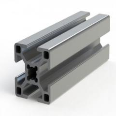
Machine frames and structural framing systems—the T-slot profiles common in automation equipment—typically specify wall thicknesses from 2.0mm to 4.0mm. These profiles must resist bending moments from cantilevered loads, withstand repeated stress cycles from moving equipment, and provide adequate thread engagement for fasteners. The wall thickness directly determines both moment of inertia (stiffness) and section modulus (strength), making it a primary design variable rather than a manufacturing constraint.
Heat sink applications flip the optimization entirely. Thermal management for electronics and power systems demands maximum surface area with minimum thermal resistance—which translates to thin fins with the smallest practical base thickness. According to industry references, specialized heat sink profiles can achieve fin thicknesses as low as 0.5mm to 0.8mm when properly designed. The thermal conductivity of aluminum (roughly 205 W/m·K for 6063 alloy) means even thin sections transfer heat effectively, making manufacturing capability—not thermal performance—the limiting factor.
Automotive applications occupy middle ground with increasingly aggressive lightweighting targets. Crash management structures require carefully calibrated wall thicknesses that crush predictably during impact, absorbing energy through controlled deformation. These profiles often specify walls from 1.5mm to 2.5mm with tight tolerances, because wall thickness variation directly affects crash performance consistency. Battery enclosure profiles for electric vehicles balance structural requirements against weight penalties, with walls typically ranging from 2.0mm to 4.0mm depending on mounting and protection requirements.
Electronics enclosures demonstrate how aesthetic and functional requirements intersect. Consumer electronics demand thin, lightweight housings—often pushing toward 0.8mm to 1.2mm walls—while still providing EMI shielding, structural rigidity, and thermal dissipation. The challenge intensifies when profiles must accommodate snap-fit features, screw bosses, or integrated heat spreading fins within these thin wall constraints.
| Application Category | Typical Wall Thickness Range | Primary Design Drivers | Key Considerations |
|---|---|---|---|
| Architectural Windows/Doors | 1.2mm - 2.0mm | Wind load resistance, weatherseal compression | Thermal break compatibility, finish durability, code compliance |
| Curtain Wall Systems | 2.0mm - 3.0mm | Span capability, deflection limits | Connection details, thermal performance, facade engineering |
| Decorative/Trim Profiles | 0.8mm - 1.2mm | Minimum weight, material cost | Handling during installation, substrate support requirements |
| Machine Frames/T-Slot | 2.0mm - 4.0mm | Load capacity, fastener engagement | Fatigue resistance, modular connection compatibility |
| Heat Sinks | 0.5mm - 1.5mm (fins) | Thermal dissipation, surface area | Fin aspect ratio limits, base thickness for mounting |
| Automotive Structural | 1.5mm - 2.5mm | Crash performance, weight optimization | Tolerance control for consistent energy absorption |
| Battery Enclosures (EV) | 2.0mm - 4.0mm | Protection, structural mounting | Sealing interface requirements, thermal management integration |
| Electronics Enclosures | 0.8mm - 1.5mm | Weight, EMI shielding, aesthetics | Feature integration, surface finish quality, assembly methods |
| Solar Panel Frames | 1.0mm - 1.4mm | Cost optimization, corrosion resistance | Snow/wind load requirements, mounting system compatibility |
| Transportation/Rail | 2.0mm - 5.0mm | Structural integrity, fatigue life | Weld preparation, crash safety standards, vibration resistance |
Notice how the ranges overlap across categories—a 2.0mm wall serves vastly different purposes in a curtain wall mullion versus a machine frame profile. The table illustrates that wall thickness specifications emerge from application requirements, not arbitrary manufacturing preferences.
For engineers and designers making real-world decisions, start with your application's non-negotiable requirements: What loads must the profile resist? What thermal performance is required? What aesthetic standards apply? Then work backward to wall thickness specifications that satisfy these requirements while remaining within stable manufacturing windows for your chosen alloy and profile geometry.
The next step—translating your optimized specification into a successful manufacturing partnership—requires understanding how to evaluate supplier capabilities and ask the right questions during the quoting process.
You've done the engineering homework—selected your alloy, optimized profile geometry, and determined the wall thickness your application requires. But here's where many projects stumble: translating those carefully developed specifications into a successful manufacturing partnership. The difference between a supplier who delivers consistent thin wall quality and one who creates ongoing headaches often comes down to asking the right questions before you commit.
What separates a capable thin wall extrusion partner from one that will struggle with your specifications? It's not just about equipment lists or certifications—it's about demonstrated experience, integrated capabilities, and transparent communication about what's achievable versus what's aspirational.
When you're sourcing aluminum extrusion assembly components or standalone profiles with aggressive wall thickness targets, supplier evaluation requires looking beyond surface-level qualifications. According to industry best practices, press capacity defines what profiles a supplier can realistically produce—and for thin wall work, press diversity matters as much as maximum tonnage.
Imagine you're specifying a complex thin-walled profile. A manufacturer with only mid-range presses might accept your order but struggle with production stability. Conversely, a supplier operating 35 extrusion presses spanning 600T to 5500T—like Shengxin Aluminium—can match your specific profile requirements to optimal equipment. Smaller presses handle precision thin-wall work where delicate control matters; larger presses tackle profiles where adequate force ensures complete die filling.
But equipment alone doesn't guarantee thin wall success. What really matters is how suppliers integrate their capabilities across the entire production chain. When evaluating potential partners, assess these critical factors:
Surface treatment capabilities deserve special attention for thin wall projects. Will anodizing, powder coating, or PVDF finishing compromise your dimensional stability? Not when properly processed by experienced suppliers. The key lies in bath temperature control, fixture design that prevents thin wall distortion, and cure cycle optimization. A comprehensive aluminium extrusion design guide would emphasize that surface treatment success depends as much on handling expertise as on coating technology itself.
Quality control systems reveal whether a supplier can maintain thin wall consistency across production runs. Look for dimensional inspection per EN755-9 standards, CMM documentation, and traceable lot data. For thin walls specifically, ask about statistical process control—tracking dimensional trends helps identify die wear before tolerances drift out of specification.
Sounds straightforward? The real insights emerge from the questions you ask during the quoting process. Experienced procurement professionals know that how suppliers answer matters as much as what they answer. Hesitation, vague responses, or overpromising on challenging specifications all signal potential problems ahead.
Before finalizing any thin wall extrusion partnership, work through these essential questions:
About capabilities and experience:
About process control:
About quality and documentation:
The information you provide shapes the quality of responses you receive. Complete RFQs accelerate accurate quoting and reveal supplier competence. Include detailed drawings with GD&T callouts, specify your alloy and temper requirements, define surface finish expectations, and clarify annual volume projections. Explain what are aluminum extrusions used for in your application—context helps suppliers identify potential manufacturing challenges before they become production problems.
For projects requiring secondary operations, confirm end-to-end capability. Can your supplier handle how to cut aluminum extrusion lengths to tight tolerances? Do they offer precision drilling, tapping, or complex CNC machining? Integrated deep processing—from die development through mass production and finishing—eliminates the coordination headaches and quality risks that multiply when profiles travel between multiple vendors.
When reviewing any aluminium extrusion design guide for specification development, remember that the theoretical minimums published in reference charts assume ideal conditions. Real-world production involves variation, and experienced suppliers build appropriate margins into their capabilities. A manufacturer who confidently quotes your aggressive thin wall specification after reviewing complete documentation—and explains exactly how they'll achieve it—deserves more consideration than one who accepts any specification without technical discussion.
The partnership you establish during the quoting process sets the tone for your entire project. Suppliers who provide DFM feedback, suggest cost optimization opportunities, and proactively identify potential issues demonstrate the collaborative approach that thin wall success requires. That transparency—asking the right questions and evaluating the answers critically—transforms what is aluminum extrusions sourcing from a transactional purchase into a strategic manufacturing relationship.
The minimum wall thickness for aluminum extrusion varies based on alloy, profile complexity, and circumscribing circle diameter. For small solid profiles using 6063 alloy, manufacturers can achieve walls as thin as 0.025 inches (0.64mm). Hollow profiles require thicker walls—typically starting at 0.055 inches for small shapes. Complex sections and harder alloys like 6061 require minimum walls of 0.035-0.040 inches. Production stability often demands specifications 20-30% above theoretical minimums to maintain consistent quality at scale.
ASTM B221 is the primary standard governing aluminum extrusions, covering extruded bars, rods, wire, profiles, and tubes. This specification establishes dimensional tolerances, mechanical property requirements, and testing protocols. For wall thickness tolerances specifically, the standard references Aluminum Association guidelines that vary based on profile size and complexity. Manufacturers typically provide EN755-9 dimensional inspection documentation for international projects requiring European compliance.
Alloy composition directly determines achievable minimum wall thickness. Softer alloys like 6063 flow easily through die openings, enabling walls down to 0.64mm. Higher-strength alloys resist deformation—6061 requires approximately 40-60% thicker walls than 6063, while aerospace-grade 7075 needs walls exceeding 1.27mm. This relationship exists because higher magnesium, silicon, and copper content increases material resistance during extrusion, limiting how thin sections can reliably form.
Hollow profiles demand thicker walls due to complex die construction and material flow dynamics. The aluminum must split around mandrel bridges, flow through the die, and rejoin in a weld chamber—creating seams that require adequate material thickness for complete fusion. Additionally, mandrel assemblies deflect under extrusion pressure, and thin walls amplify dimensional variations. Industry data shows hollow profiles typically require 25-56% thicker walls than equivalent solid shapes depending on size.
Evaluate suppliers based on press range diversity (600T-5500T allows optimal equipment matching), in-house die design capability, billet quality control protocols, and demonstrated thin wall experience. Request scrap rate data and CPK documentation from similar projects. Integrated capabilities matter—manufacturers offering end-to-end support from die development through CNC machining and surface treatment can maintain tighter control over thin wall dimensional stability throughout the production chain.



 Інтернет-сервіс
 0086 136 3563 2360
 sales@sxalu.com
 +86 136 3563 2360
 Українська
 English
 français
 Deutsch
 русский
 español
 português
 العربية
 ไทย
 Việt