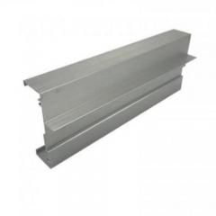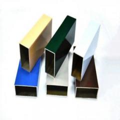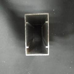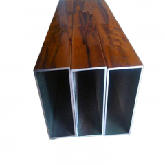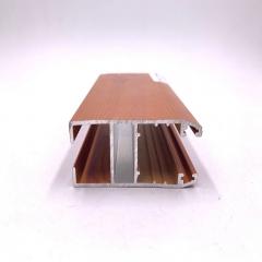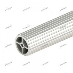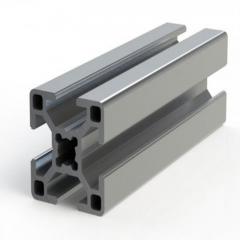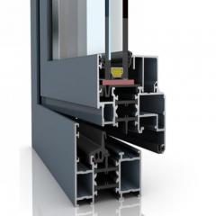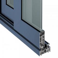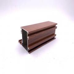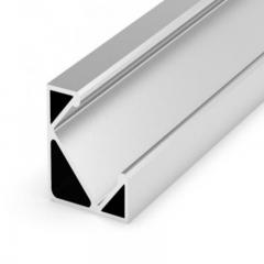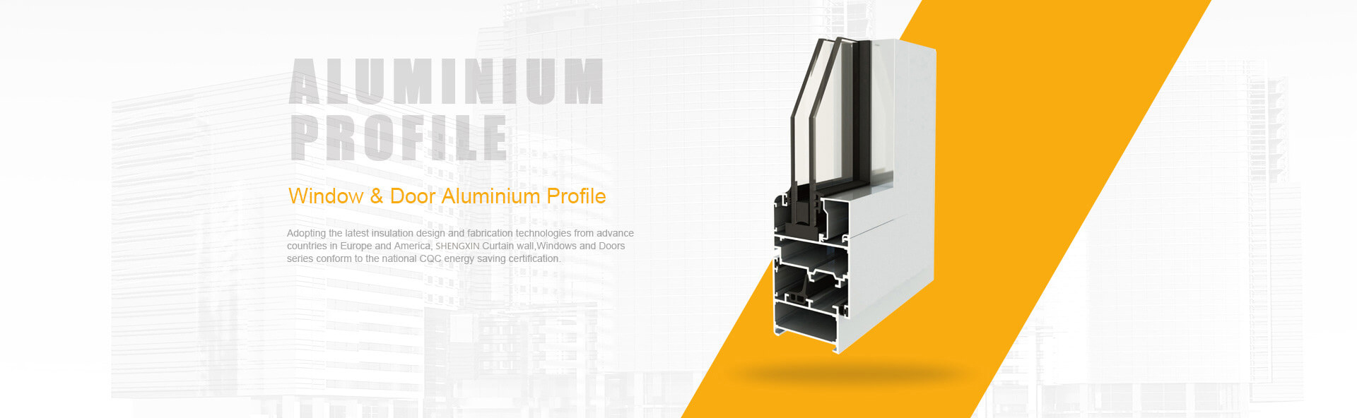
Ever wondered how those precisely shaped aluminum profiles in window frames, electronic enclosures, or industrial machinery come to life? The answer lies in understanding aluminum extrusion design—a discipline that bridges creative engineering with manufacturing reality.
Aluminum extrusion design is the engineering process of creating custom cross-sectional profiles by specifying how heated aluminum billets will be forced through shaped steel dies under high pressure, resulting in continuous shapes with consistent dimensions and properties.
When you define extruded aluminum in practical terms, you're describing a manufacturing method similar to squeezing toothpaste through a tube—except the "tube" is a precision-engineered die, and the result is a structural component ready for real-world applications. This aluminum extrusion definition applies whether you're working with simple angles or complex architectural systems.
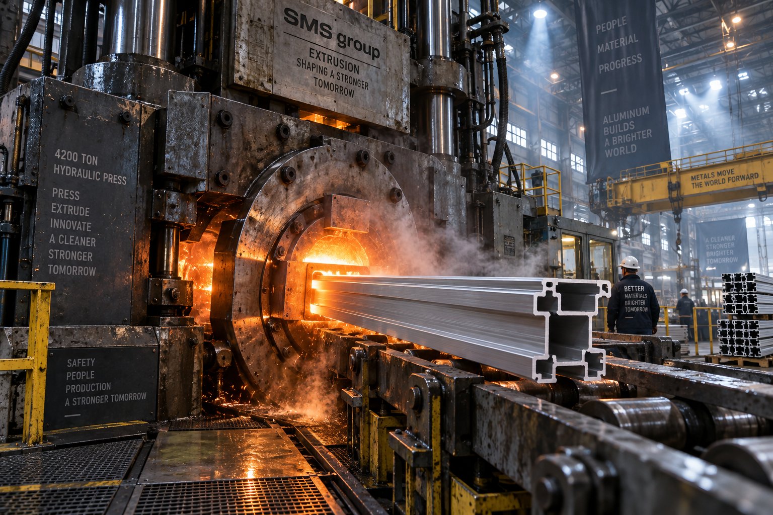
The fundamental process works like this: a cylindrical aluminum billet is heated to approximately 800-925°F, making it malleable without becoming molten. A hydraulic ram then applies immense pressure—sometimes up to 15,000 tons—forcing the softened metal through a custom die. What emerges is your designed profile, perfectly formed and ready for cooling, cutting, and finishing.
For engineers, understanding this aluminium extrusion definition goes beyond the basic mechanics. Your design decisions directly influence die complexity, production speed, and ultimately, project costs. That's why this guide takes a design-centric approach rather than focusing solely on manufacturing operations.
Why do engineers across industries consistently specify aluminum extrusion profiles? Consider these compelling advantages:
From architectural curtain walls to automotive chassis components, from electronic heat sinks to renewable energy mounting systems, aluminum extrusion applications span virtually every industry. This guide provides the practical, actionable guidance you need to move from concept to production-ready profiles—covering alloy selection, dimensional constraints, manufacturability optimization, and effective manufacturer partnerships.
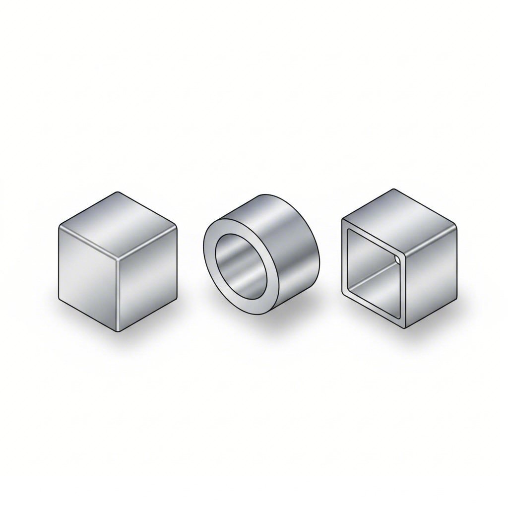
Before diving into alloy chemistry or dimensional tolerances, you need to master the fundamental vocabulary of aluminum extrusion shapes. Every profile you design falls into one of three classifications—solid, hollow, or semihollow—and understanding these distinctions directly impacts your die costs, production timeline, and design possibilities.
Why does this classification matter? Because the shape category determines which type of die is required, how complex the tooling becomes, and ultimately how much you'll invest in bringing your design to life. When browsing an extruded aluminum shapes catalog, you'll notice these categories organize everything from simple bars to intricate multi-void tubes.
A solid profile is any aluminum extrusion shape that doesn't enclose a void—think of flat bars, angles, channels, T-sections, and complex decorative trim pieces. Despite being the "simplest" category, solid profiles represent enormous design flexibility that many engineers overlook.
What makes solid extrusions particularly attractive for your project?
Solid profiles aren't limited to basic shapes. Creative designers use them for heat sinks with intricate fin patterns, decorative architectural elements, and structural members with strategically placed metal exactly where load demands it. The key is recognizing that "solid" doesn't mean "simple"—it means freedom from enclosed voids.
When your design requires enclosed voids—tubes, multi-cell profiles, or partially enclosed channels—you enter the world of hollow and semihollow classifications. These types of aluminum extrusions demand more sophisticated tooling and deeper understanding of industry standards.
Hollow profiles completely enclose one or more voids. According to Aluminum Association standards, they're subdivided into three classes:
Semihollow profiles partially enclose a void without fully closing it. Imagine a C-channel with a very narrow gap—is it a solid or a semihollow? The answer depends on the tongue ratio, calculated by dividing the area of the partially enclosed void by the square of the gap width (Area/Gap²).
Semihollow classifications break down into two types:
The tongue ratio thresholds vary by gap width and alloy group. For 6000-series alloys with gap widths between 0.125 and 0.249 inches, a Class 1 semihollow requires a tongue ratio of 3.5 or higher, while Class 2 requires only 3.0. If your ratio falls below these thresholds, the profile is classified as solid despite partially enclosing a void.
| Factor | Solid Profiles | Semihollow Profiles | Hollow Profiles |
|---|---|---|---|
| Die Complexity | Single-piece flat or pocket die | May require porthole die with tongue support | Two-piece porthole die (mandrel + cap) |
| Relative Die Cost | Lowest | Moderate | Highest |
| Typical Applications | Bars, angles, heat sinks, trim | Deep channels, snap-fit features | Tubes, structural members, enclosures |
| Design Flexibility | High—asymmetry and varying thicknesses possible | Moderate—tongue strength limits depth | High for internal voids, constrained by weld lines |
| Production Speed | Fastest | Moderate | Slowest (especially Class 3) |
Understanding these aluminum extrusions shapes classifications helps you communicate effectively with manufacturers and anticipate project costs. When designing semihollow features, pay close attention to tongue ratio requirements—pushing too close to classification thresholds can compromise die longevity and increase the risk of tongue breakage during production. A slightly wider gap or shallower void might shift your design into a more manufacturable category, reducing both tooling costs and production headaches.
You've classified your profile as solid, hollow, or semihollow—now comes the question that trips up even experienced engineers: how thin can you actually go? Wall thickness decisions ripple through every aspect of your project, from structural performance to production feasibility. Get this wrong, and you'll face rejected designs, costly die modifications, or profiles that warp during heat treatment.
Understanding aluminum extrusion dimensions isn't about memorizing tables—it's about grasping the relationship between wall thickness, profile size, alloy selection, and achievable tolerances. Let's break down these constraints in practical terms you can apply immediately.
Here's a reality check: minimum wall thickness isn't a single number. It depends on three interconnected factors—your chosen alloy, the circumscribing circle diameter (CCD) of your profile, and whether you're designing solid or hollow sections.
For the workhorse alloys in standard aluminum extrusions, here's what you can realistically specify:
Why does alloy matter so much? Lower-extrudability alloys require higher die face pressures and slower extrusion speeds. Thin walls in these materials can't maintain structural integrity during quenching and subsequent handling, leading to distortion or surface defects.
Imagine the smallest circle that completely encloses your profile's cross-section—that's your circumscribing circle diameter, and it determines which presses can produce your design and what tolerances are achievable.
Most extrusion facilities optimize for standard aluminium extrusions with CCDs between 20mm and 250mm. Within this range, you'll find competitive pricing and readily available capacity. Push beyond 300mm, and you're entering specialized territory with fewer suppliers and higher costs. Some facilities handle CCDs up to 600mm or more, but expect longer lead times and premium pricing.
The CCD also directly influences minimum wall thickness. As your profile grows larger, metal must flow farther from the die center, requiring thicker walls to maintain uniform pressure distribution. A 1.2mm wall might work beautifully in a 50mm CCD profile but cause metal flow problems and surface defects at 200mm CCD.
Beyond wall thickness and CCD, several critical dimensional considerations affect manufacturability:
What about aluminum extrusion tolerances? Standard industry tolerances from the Aluminum Association provide adequate precision for most applications. Cross-sectional dimensions typically hold ±0.15mm for features under 25mm, increasing to approximately ±1% for larger dimensions. Wall thickness tolerances run about ±10% of the specified thickness.
For extruded aluminum sizes requiring tighter control, precision tolerances are achievable but increase costs. Straightness holds to 0.3mm per 300mm length (0.0125 inches per foot), while twist tolerance is approximately 0.5 degrees per 300mm. Flatness across profile surfaces runs ±0.1mm per 25mm of width.
When specifying extruded aluminum channel shapes or other standard sections, remember that tolerances compound. A dimension spanning multiple walls or gaps accumulates the tolerances of each element. Design critical interfaces with metal-to-metal dimensions wherever possible—they're easier to hold precisely than gap dimensions.
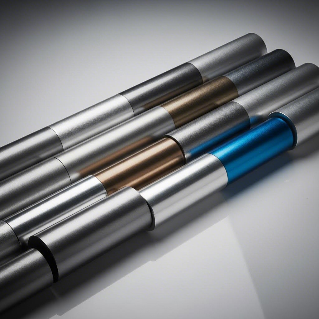
You've nailed down your profile geometry and verified wall thickness feasibility—but here's where many aluminum extrusion design projects go sideways. Choosing the wrong alloy doesn't just affect mechanical properties; it cascades into die design complications, surface finish limitations, and unexpected processing headaches. Yet surprisingly, most technical guides gloss over alloy selection with vague recommendations like "consult your manufacturer."
Let's fix that. This framework gives you the decision-making tools to specify aluminum extrusion alloys with confidence, matching material properties to your actual application demands rather than defaulting to whatever seems familiar.
Think of alloy selection as answering a series of prioritization questions. What matters most for your application—structural strength, surface appearance, corrosion resistance, or ease of fabrication? Your answers determine which alloy family deserves attention.
The aluminium extrusion process responds differently to each alloy's chemistry. Elements like magnesium, silicon, copper, and zinc alter how metal flows through dies, how quickly profiles can be extruded, and what surface quality emerges on the other side. Understanding these relationships helps you anticipate manufacturing constraints before they become project delays.
Here's how the most common extrusion alloys compare across the factors that actually matter for design decisions:
| Property | 6063 | 6061 | 6005/6005A | 6082 |
|---|---|---|---|---|
| Extrudability | Excellent—fastest speeds, thinnest walls | Good—moderate speeds, requires thicker walls | Good—bridges gap between 6063 and 6082 | Fair—slower speeds, more die wear |
| Tensile Strength (T6) | ~30,000 psi minimum | ~42,000 psi minimum | ~38,000 psi minimum | ~42,000 psi minimum |
| Yield Strength (T6) | ~25,000 psi minimum | ~35,000 psi minimum | ~35,000 psi minimum | ~35,000 psi minimum |
| Surface Finish Quality | Excellent—smooth, uniform appearance | Good—may show minor extrusion lines | Good—slightly less consistent than 6063 | Fair—more visible surface variations |
| Anodizing Response | Excellent—most uniform color, ideal for decorative finishes | Good—acceptable for protective anodizing | Good—performs well with proper control | Fair—requires tighter process control |
| Weldability | Excellent | Good | Good | Good |
| Typical Applications | Architectural trim, window frames, decorative elements | Structural frames, truck bodies, marine components | Rail profiles, ladder frames, structural tubing | Highly stressed structural parts, bridges |
Notice the pattern? As strength increases, extrudability and surface finish quality tend to decrease. This tradeoff isn't arbitrary—it stems from the extrusion aluminium process itself. Stronger alloys resist deformation, requiring higher pressures that accelerate die wear and limit achievable detail.
This comparison comes up constantly, and for good reason—these two aluminium extrusion types cover the vast majority of applications. Here's how to make the call:
Choose 6063 when:
Choose 6061 when:
According to Eagle Aluminum's technical comparison, 6061-T6 delivers ultimate tensile strength of at least 42,000 psi versus 6063-T6's 28,000 psi minimum. That 50% strength advantage makes 6061 the clear choice for load-bearing structures—but it comes with tradeoffs in extrudability and surface quality that affect both cost and aesthetics.
How alloy choice affects your die design and production:
Your alloy selection directly influences manufacturing parameters in ways that affect project timeline and budget:
Downstream processing compatibility:
Your alloy decision doesn't end at the extrusion press. Consider how the profile will be finished and assembled:
Looking at real-world extrusion examples, architectural window systems almost universally specify 6063 for its combination of extrudability, surface quality, and anodizing response. Meanwhile, industrial equipment frames and structural applications gravitate toward 6061 or 6005 where strength requirements justify the manufacturing tradeoffs.
The bottom line? Match your alloy to your primary performance requirement, then verify that secondary needs are adequately met. When strength and aesthetics both matter significantly, consider designing for 6005 or 6005A—these alloys bridge the gap between 6063's workability and 6061's mechanical properties, offering a practical compromise that many engineers overlook.
You've selected your alloy, verified your wall thicknesses, and feel confident about your profile geometry. But here's the question that separates good designs from great ones: will your aluminum extrusion die survive thousands of production cycles without degradation? Design for Manufacturability (DfM) isn't just about whether a profile can be extruded—it's about whether it can be produced efficiently, consistently, and economically over the long haul.
Think of it this way: every design decision you make at the profile stage ripples forward into die complexity, production speed, and ultimately your per-piece costs. The aluminium extrusion design guidelines that follow will help you create profiles that perform beautifully in application while keeping your manufacturing partners happy and your budget intact.
Your aluminum extrusion die represents a significant upfront investment—typically $500 to $3,000 for standard profiles, potentially more for complex geometries. But the real cost isn't just the die itself; it's what happens when poor design choices cause premature wear, breakage, or inconsistent output that requires frequent correction.
What makes one die last for hundreds of thousands of feet while another fails after a few production runs? The answer lies in how your profile geometry distributes stress across the die face. Here are the core principles that extend die life:
According to a comprehensive study of 616 die failures, the majority stem from predictable design issues rather than manufacturing defects. Addressing these concerns at the design stage costs nothing—fixing them after die construction requires expensive modifications or complete replacement.
Even experienced engineers fall into traps that complicate manufacturing. Here's what to watch for—and how to avoid these costly mistakes:
Pitfall 1: Over-specifying tolerances
Requesting tighter tolerances than your application actually requires drives up costs without adding value. Standard aluminum extrusion tolerances (±0.15mm for small features, ±10% for wall thickness) satisfy most applications. Before specifying precision tolerances, ask yourself: will the assembly actually fail if this dimension varies within standard limits?
Pitfall 2: Ignoring metal flow physics
Metal doesn't flow uniformly through complex die geometries. Thin walls adjacent to thick sections, deep narrow channels, and unsupported cantilevers all create flow imbalances that manifest as dimensional variations, surface defects, or outright production failures. Imagine the aluminum as viscous fluid seeking the path of least resistance—then design accordingly.
Pitfall 3: Neglecting secondary operations
Your extrusion doesn't exist in isolation. Will it be machined? Welded? Anodized? Each downstream process imposes constraints. For example, if you need to know how to cut aluminum extrusion cleanly, your profile should provide adequate material for saw blade kerf without creating thin, unsupported sections prone to burring or deformation.
Pitfall 4: Creating non-symmetrical shapes without justification
Asymmetric profiles aren't impossible—but they require more sophisticated die design to achieve balanced metal flow. According to MMG's design guide, asymmetric shapes rank among the most common design issues manufacturers encounter. If symmetry serves your functional requirements, embrace it.
Understanding how profile complexity affects costs helps you make informed tradeoffs:
Communicating effectively with your extrusion partner:
The best aluminum extrusion design guide in the world can't replace early collaboration with your manufacturer. Here's how to make those conversations productive:
Remember, raw material costs constitute approximately 90% of basic extrusion expenses. Every design decision that improves material utilization—eliminating unnecessary thickness, reducing scrap, enabling faster production—directly impacts your bottom line. Manufacturability isn't the enemy of innovation; it's the foundation that makes innovative designs economically viable.
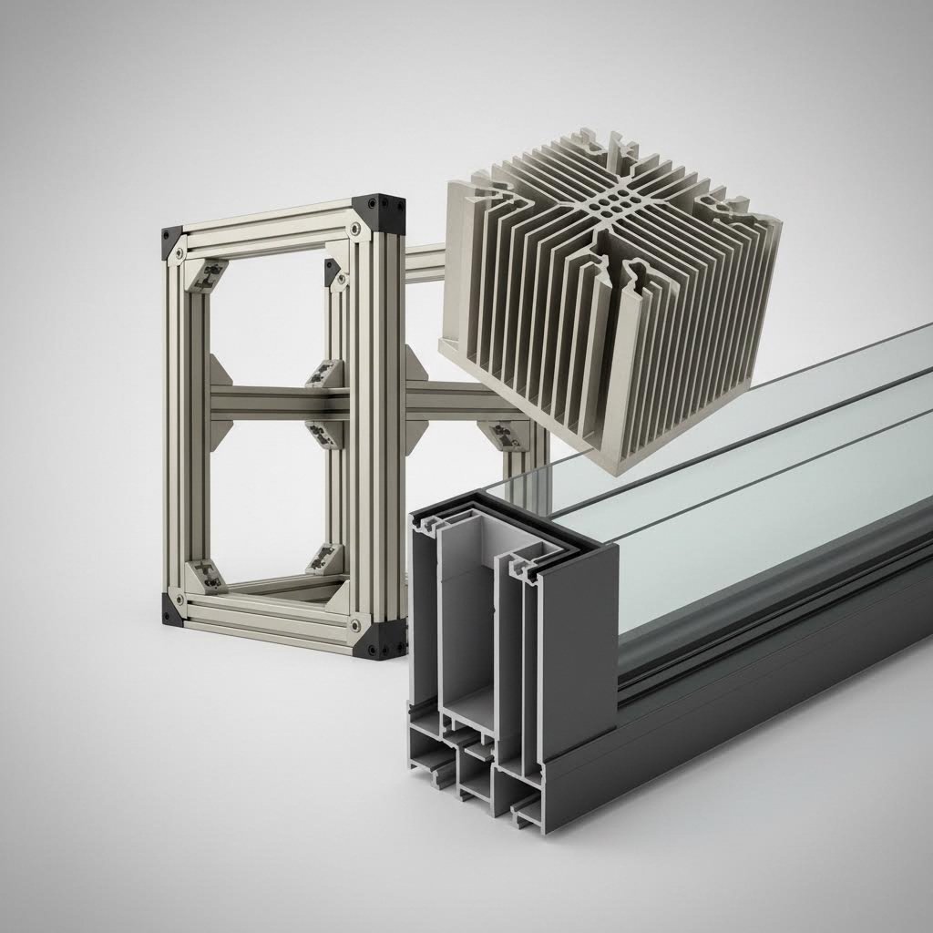
You've mastered the fundamentals—profile classifications, wall thickness constraints, alloy selection, and manufacturability principles. Now comes the question that truly matters: how do these elements come together for your specific application? The aluminum extrusions definition encompasses far more than manufacturing technique; it represents a design solution that adapts to radically different performance demands across industries.
Rather than presenting abstract technical categories, let's walk through the real-world aluminum extrusion applications that drive profile geometry, material choices, and surface treatment decisions. Your industry dictates your priorities—and understanding those priorities transforms good designs into exceptional ones.
When you're designing for architectural systems—window frames, curtain walls, storefronts, or decorative facades—aesthetics and durability share the spotlight with structural performance. These applications represent some of the most demanding aluminum extrusion design challenges because failures are visible, permanent, and expensive to remediate.
What makes architectural extrusions unique? Consider a curtain wall system: it must resist wind loads, accommodate thermal expansion, prevent water infiltration, meet energy codes, and look flawless for decades. That's a tall order for any material system.
Key design considerations for building with aluminum extrusion in architectural applications:
Alloy selection for architectural work almost always lands on 6063-T5 or T6 for its exceptional extrudability, surface finish quality, and anodizing response. Only specify 6061 when structural calculations absolutely demand higher strength—and expect to sacrifice some aesthetic consistency in anodized finishes.
Shift from architecture to industrial applications, and your priorities transform dramatically. Here, structural aluminum extrusions must deliver precise load capacity, modular assembly, and often accommodate frequent reconfiguration. The 8020 extrusion approach—named after a pioneering T-slot manufacturer—has become synonymous with modular aluminum framing.
T-slot and structural framing considerations:
Heat sink and thermal management profile design:
Thermal management represents a specialized aluminum extrusion application where profile geometry directly determines functional performance. According to Zetwerk's technical guide, effective heat sink design balances several competing factors:
Transportation and vehicle applications:
Weight sensitivity defines transportation applications. Every gram saved translates to improved fuel efficiency or extended battery range. Structural aluminum extrusions compete directly with steel—and often win when total system weight matters.
Across all these applications, a consistent pattern emerges: your functional requirements drive profile geometry, which influences alloy selection, which determines surface treatment options. Understanding this cascade helps you make informed tradeoffs rather than discovering conflicts late in development. The next consideration—how surface treatments impose their own design constraints—builds directly on these application-specific foundations.
You've designed your aluminum profile extrusion with perfect wall thicknesses, optimal alloy selection, and manufacturable geometry. But here's what catches many engineers off guard: your surface treatment choice can invalidate design decisions you thought were finalized. Anodizing, powder coating, and mechanical finishing each impose their own constraints on corner radii, dimensional tolerances, and even profile accessibility.
Think of surface treatment as the final design filter—one that rewards forethought and punishes assumptions. Understanding these implications before finalizing your extruded aluminum profile geometry saves costly redesigns and ensures your finished components meet both aesthetic and functional requirements.
Anodizing converts the aluminum surface into a hard, corrosion-resistant oxide layer that becomes integral to the metal itself. Unlike coatings that sit on top, anodic films grow both inward and outward from the original surface. This growth behavior directly affects your dimensional planning.
For decorative Class I architectural anodizing (0.7 mil minimum thickness), expect the extruded aluminum profiles to grow approximately 0.0005 inches per surface. That sounds trivial—until you're designing precision-fit assemblies where multiple anodized surfaces interface. A mating joint between two anodized parts gains nearly 0.002 inches in total gap reduction.
Design considerations specific to anodized aluminum sections:
Color consistency presents unique challenges for alum extrusion shapes requiring decorative finishes. Electrolytic coloring processes deposit metal salts within the porous oxide layer, and slight variations in alloy chemistry or extrusion parameters manifest as visible color differences. When specifying colored anodizing, discuss acceptable color tolerance ranges (typically measured in Delta E values) with both your extruder and anodizer.
Powder coating and PVDF (polyvinylidene fluoride) finishes sit atop the aluminum rather than integrating with it—but don't assume this makes design any simpler. These coatings impose their own geometric constraints and add measurable thickness that affects dimensional planning.
Standard powder coating adds 2-4 mils (0.002-0.004 inches) per surface, while premium PVDF architectural finishes typically run 1-1.5 mils. Unlike anodizing's predictable growth pattern, coating thickness varies with application method, profile geometry, and operator technique.
Design considerations for painted aluminum profile extrusion:
PVDF coatings offer superior weathering resistance compared to standard polyester powders, making them the preferred choice for architectural facades exposed to UV and environmental degradation. However, PVDF requires specialized application equipment and higher curing temperatures—factors that may limit your supplier options.
Specifying surface treatments in technical documentation:
Clear specifications prevent misunderstandings that lead to rejected parts or compromised performance. Your drawings and specifications should include:
Remember that surface treatment adds both cost and lead time to your project. Anodizing typically requires 3-5 days after extrusion, while powder coating may add 2-4 days depending on color complexity and batch sizes. Factor these timelines into your project planning—and recognize that surface treatment selection affects far more than just appearance.
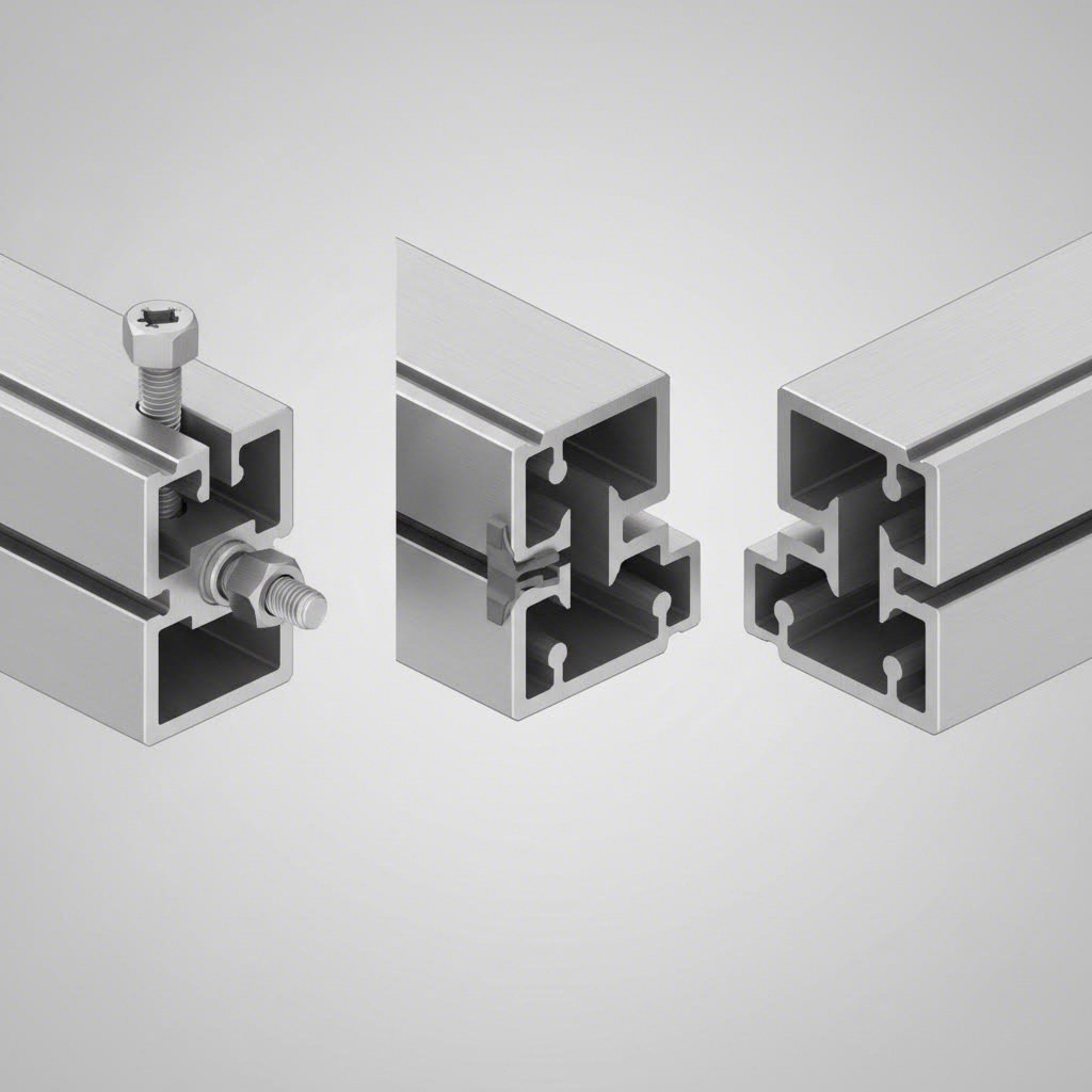
Here's a reality most aluminum extrusion design guides overlook: your profile geometry means nothing if you can't assemble it effectively. The strongest extruded aluminum sections become weak links when connections fail—and connection design often determines whether your assembly thrives under load or rattles loose within months. Understanding how to integrate connection features directly into your profile transforms aluminum extrusion assembly from an afterthought into a strategic advantage.
Why does this matter so much? Because an assembly is only as strong as its connections. According to research on aluminum framing systems, T-slot extrusion fasteners that rely on friction at a single plane of contact inherently reduce the effective strength of connected profiles. Design your connection strategy upfront, and you'll avoid costly retrofits and performance compromises down the line.
Imagine designing your extruded shape with built-in assembly intelligence—screw channels positioned exactly where fasteners need them, snap-fit geometries that eliminate hardware entirely, and interlocking features that self-locate during assembly. This is the power of integrated connection design.
T-slot channel integration:
T-slots remain the most versatile connection feature for structural extruded aluminum applications. When designing T-slot channels into your profile, consider these critical factors:
Snap-fit joint design:
Snap-fit connections offer tool-free assembly and easy disassembly—ideal for applications requiring frequent reconfiguration. Industry guidance confirms that snap-fit designs reduce the need for additional components like fasteners or adhesives, simplifying the assembly process considerably.
Effective snap-fit features require careful attention to:
Screw boss and fastener channel integration:
Designing screw bosses directly into extruded shapes eliminates secondary drilling operations and ensures consistent fastener positioning. Size bosses to accommodate standard thread-forming or thread-cutting screws, with wall thickness adequate to develop full thread engagement without cracking.
Your assembly method choice cascades backward into profile design requirements. Selecting the wrong joining approach forces design compromises—or worse, leads to field failures. Here's how the major connection methods compare:
| Connection Method | Profile Design Requirements | Load-Bearing Characteristics | Best Applications |
|---|---|---|---|
| Mechanical Fasteners (bolts, rivets) | Requires flat mating surfaces, adequate edge distance (2x fastener diameter minimum), material thickness for thread engagement | High tensile and shear strength; reversible; predictable performance | Structural frames, equipment mounts, assemblies requiring service access |
| Welding (MIG/TIG) | Minimum 3mm wall thickness at weld zones; remove anodizing from weld areas; design for weld accessibility | Highest joint strength; permanent; creates heat-affected zone that loses T6 temper properties | Permanent structural joints, sealed enclosures, high-stress applications |
| Adhesive Bonding | Requires clean, flat bonding surfaces; design for adequate bond area; avoid peel loading | Excellent fatigue resistance; distributes stress across bond area; no heat damage | Thin profiles, dissimilar material joining, vibration-sensitive assemblies |
| Snap-Fit Joints | Integrated cantilever features with controlled deflection; adequate wall thickness at hook roots | Moderate retention force; quick assembly/disassembly; best for low-stress applications | Covers, access panels, modular assemblies, consumer products |
Welding considerations for aluminum profiles:
While welding creates exceptionally strong joints, it introduces design constraints unique to aluminum. Technical analysis confirms that welding aluminum causes it to anneal, mitigating heat treatment benefits in the affected zone. Your profile design must account for this strength reduction—typically by increasing wall thickness at weld locations or positioning welds away from high-stress areas.
Adhesive bonding advantages:
For thin or delicate extruded aluminum sections, adhesive bonding offers compelling benefits. The process produces smooth, clean joints without heat damage to the aluminum. Industry experts recommend ensuring surfaces are properly cleaned and treated to remove oxide layers before applying adhesives—epoxies and polyurethanes are particularly effective for aluminum bonding.
Tolerance stack-up in multi-component assemblies:
Every connection point introduces dimensional variation. When multiple extruded shapes join to form complex assemblies, these variations compound—a phenomenon called tolerance stack-up that can transform acceptable individual tolerances into unacceptable assembly-level deviations.
Managing tolerance stack-up requires strategic thinking:
Remember that conventional T-slot systems using bolts as locating devices between assembly plates and extrusions can produce angular misalignment of up to ±0.50mm per 25mm length. For precision assemblies, this level of variation is often unacceptable—specify tighter-tolerance connection systems or incorporate post-assembly machining of critical interfaces.
The bottom line? Your connection strategy deserves as much design attention as your profile geometry. Integrated connection features, properly matched assembly methods, and realistic tolerance analysis transform individual extrusions into reliable, high-performance assemblies that deliver lasting value.
You've invested significant effort in aluminum extrusion design—optimizing geometry, selecting alloys, planning connections. But here's where theory meets reality: translating your design intent into production-ready aluminum extrusions requires a manufacturing partner who understands both your specifications and the practical constraints of the extrusion process. The right partnership transforms good designs into exceptional products; the wrong one leads to costly revisions, quality issues, and project delays.
So what is aluminum extrusions manufacturing really about from a partnership perspective? It's a collaborative process where your design expertise meets your manufacturer's production knowledge. Understanding this workflow—from initial concept through die development, sampling, and mass production—helps you communicate effectively and evaluate potential partners with confidence.
Effective communication starts before you send your first drawing. Manufacturers can't optimize what they don't understand, so sharing context alongside specifications dramatically improves outcomes.
What to communicate beyond the drawing:
According to industry best practices, strong technical communication differentiates professional suppliers from traders. A capable extrusion factory will provide Design for Manufacturability (DfM) feedback on drawings, offer feasibility and cost optimization suggestions, and share inspection photos, reports, and videos before shipment. Procurement managers value suppliers who proactively prevent issues instead of reacting after defects occur.
The typical aluminum extrusion projects workflow:
Understanding the production sequence helps you plan realistic timelines and identify decision points:
Total lead time for standard aluminum extrusion projects typically runs 4-6 weeks from order placement to shipment. Complex profiles or specialty alloys may extend this timeline—discuss scheduling early to avoid surprises.
The transition from prototype to production scaling reveals whether your manufacturing partner can truly support your project's growth. What works for 500 feet may not scale to 50,000 feet without process adjustments, and partners with limited capabilities become bottlenecks as your volumes increase.
Key criteria for evaluating extrusion aluminum manufacturing partners:
To define aluminum extrusion partnership success, consider what full-service support actually looks like in practice. For complex custom profiles requiring tight tolerances, integrated machining, and premium surface finishes, end-to-end manufacturing capability becomes essential. Companies like Shengxin Aluminium exemplify this approach with 35 extrusion presses ranging from 600T to 5500T, enabling production of profiles from delicate architectural trim to heavy structural members. Their integrated CNC machining centers handle precise cutting, drilling, and bending, while comprehensive surface treatment options—including anodizing in custom colors and powder coating—complete profiles without external subcontracting delays.
Questions to ask potential manufacturing partners:
The value proposition of comprehensive manufacturing partnerships extends beyond convenience. When die development, extrusion, machining, and finishing occur under unified quality control, accountability stays clear and finger-pointing between subcontractors disappears. For engineers asking what are aluminum extrusions used for in demanding applications—aerospace components, precision industrial equipment, architectural systems with tight aesthetic requirements—this integrated approach often makes the difference between acceptable results and exceptional ones.
Your aluminum extrusion design journey doesn't end when you finalize specifications. It continues through partnership with manufacturers who understand your intent, possess the capabilities to execute your vision, and provide the technical support to optimize both performance and cost. Choose partners who invest in understanding your application, offer proactive DfM guidance, and demonstrate the breadth of capability to support your project from prototype through high-volume production.
Effective aluminum extrusion design follows key DfM principles: use symmetrical profiles when possible for balanced metal flow, specify gradual thickness transitions (blend radii at least 3x the thickness difference), maintain minimum corner radii of 0.5mm for internal corners and 0.3mm for external corners, and keep wall thickness ratios below 3:1. Always communicate with your extrusion manufacturer early, sharing application context and identifying critical versus nominal dimensions. These practices extend die life, reduce production costs, and ensure consistent quality across production runs.
Choose 6063 aluminum when surface appearance matters—it offers excellent extrudability, superior anodizing response, and allows thinner walls for complex profiles. It's ideal for architectural elements and decorative applications. Select 6061 when structural integrity under significant loads is essential—it delivers approximately 50% higher tensile strength (42,000 psi vs 28,000 psi minimum). However, 6061 requires approximately 25% thicker walls, runs at slower extrusion speeds, and may show minor surface variations. For applications needing both strength and aesthetics, consider 6005 or 6005A as a practical compromise.
Minimum wall thickness depends on alloy type and circumscribing circle diameter (CCD). For 6063 alloy with CCDs under 25mm, walls as thin as 1.0mm are achievable; this increases to 1.5mm at 100mm CCD and 2.0-2.5mm for profiles with 150-200mm CCD. Stronger alloys like 6061 require multiplying these minimums by 1.25. Internal webs in hollow profiles typically need 10-15% more thickness than external walls to ensure proper metal flow and weld line integrity.
Solid profiles have no enclosed voids (bars, angles, heat sinks) and use single-piece dies—the most economical option with fastest production speeds. Hollow profiles completely enclose one or more voids (tubes, multi-cell sections) and require two-piece porthole dies, increasing tooling costs by 50-100%. Semihollow profiles partially enclose voids without fully closing them, classified by tongue ratio calculations. Understanding these categories helps predict die costs, production timelines, and design flexibility—solid profiles offer the most design latitude while hollow profiles enable enclosed structural geometries.
Surface treatments impose specific design constraints. Anodizing grows oxide layers both inward and outward (approximately 0.0005 inches per surface for Class I finishes), affecting dimensional planning for mating assemblies. Sharp internal corners should be avoided—specify minimum 1.0mm radii for uniform oxide growth. Powder coating adds 2-4 mils per surface and thins at sharp edges due to electrostatic effects, requiring minimum 0.5mm external corner radii. Deep recesses may receive inadequate coating coverage, so keep aspect ratios below 2:1-3:1 depending on treatment type. Alloy selection also matters—6063 produces the most uniform anodized finishes.



 Інтернет-сервіс
 0086 136 3563 2360
 sales@sxalu.com
 +86 136 3563 2360
 Українська
 English
 français
 Deutsch
 русский
 español
 português
 العربية
 ไทย
ไทย Việt
Việt