When you spot a surface crack or dimensional variation on an extruded aluminum profile, your first instinct might be to blame the press or the die. But here's the thing: that visible flaw could have originated several stages earlier in the process. Understanding aluminum extrusion defects and remedies requires tracing problems back to their true source, not just treating symptoms on the shop floor.
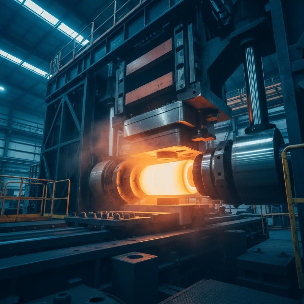
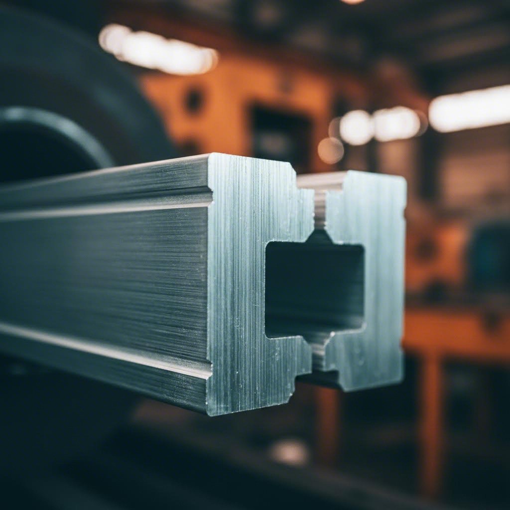
Aluminum extrusion is a process by which aluminum alloy material is forced through a die with a specific cross-sectional profile. A powerful ram pushes the heated billet through the die opening, and the metal emerges in the same shape as that opening, much like squeezing toothpaste from a tube. The resulting profiles can be solid, hollow, or semi-hollow, ranging from simple angles and channels to complex custom shapes.
Temperature is the most critical factor in this process. Billets must be heated to approximately 800-925°F before extrusion, and maintaining proper thermal conditions throughout determines surface quality, dimensional accuracy, and mechanical properties. When temperature, pressure, or speed fall outside optimal ranges, defects emerge.
Why do these flaws matter? Two reasons: structural integrity and operational cost. A surface defect might compromise coating adhesion or weld quality. A dimensional variation could mean rejected parts and production delays. For quality and procurement managers evaluating supplier output, defect rates directly translate to scrap costs and downstream assembly problems.
This guide serves two audiences. Process engineers troubleshooting active defects will find structured cause-and-remedy frameworks for each defect type. Quality and procurement managers evaluating supplier capabilities will gain a standards-based evaluation framework anchored to the Aluminum Association (AA) dimensional tolerance standards, which define what constitutes an out-of-tolerance condition for aluminum mill products.
The key concept here is the defect lifecycle. Flaws can originate at any of five stages:
Distinguishing the origin stage is the first step in any fix. A defect that looks like a die problem might actually trace back to billet contamination. A surface issue blamed on handling could stem from excessive extrusion speed.
A defect's visible symptom rarely reveals its true origin — systematic diagnosis starts upstream.
The sections that follow will walk you through defect classification, root cause analysis, and structured remedies, giving you the diagnostic tools to trace any flaw back to its source.
Before you can fix a defect, you need to name it, locate its origin, and understand how serious it is. Sounds straightforward, right? In practice, aluminum extrusion quality control gets complicated fast. A surface flaw that looks cosmetic might actually compromise coating adhesion. A dimensional variation that seems minor could cause fit problems during aluminum extrusion assembly. The table below gives you a single reference point for the most common defects, where they originate, and how to prioritize your response.
This master classification table covers 12 defects you'll encounter across billet preparation, press operations, die conditions, cooling, and post-extrusion handling. Use it as your starting point when diagnosing any quality issue, whether you're troubleshooting on the shop floor or evaluating machined aluminum extrusion from a supplier.
| Defect Name | Origin Stage | Affected Alloy Families | Severity Tier | Primary Remedy Direction |
|---|---|---|---|---|
| Die Lines | Die (bearing zone) | All alloys | Cosmetic / Functional | Die polishing, nitriding, bearing length adjustment |
| Surface Cracking | Press stage | 6061, 6082, 7xxx series | Structural | Reduce extrusion speed, optimize billet temperature |
| Blistering | Billet preparation / Press stage | All alloys | Functional / Structural | Ensure dry billets, control extrusion barrel moisture |
| Layering / Delamination | Billet preparation | All alloys | Structural | Improve billet surface cleaning, control container temperature |
| Pick-Up | Die (bearing zone) | 6063, soft alloys | Cosmetic / Functional | Clean die regularly, adjust lubrication |
| Dimensional Variation | Die / Press stage | All alloys | Functional | Optimize die design, control extrusion speed and temperature |
| Weld Seam Weakness | Die (porthole dies) | All alloys (hollow profiles) | Structural | Increase extrusion pressure, optimize die chamber design |
| Quench Distortion | Runout table / Cooling | 6061, 6082, 7xxx series | Functional | Ensure uniform cooling, adjust quench parameters |
| Tail-End Defects (Shrinkage) | Press stage (end of cycle) | All alloys | Structural | Adjust discard length, control ram speed at cycle end |
| Handling Scratches | Post-extrusion handling | All alloys | Cosmetic | Improve handling procedures, use protective coverings |
| Porosity | Billet preparation | All alloys | Structural | Improve billet quality, use ultrasonic inspection |
| Orange Peel | Press stage / Heat treatment | 6xxx series | Cosmetic / Functional | Control homogenization, reduce stretching force |
You'll notice that some defects span multiple severity tiers. Die lines, for example, might be purely cosmetic on a structural component but become functional when they interfere with anodizing uniformity. Context matters, so use this table as a starting framework rather than a rigid rulebook.
Not all defects carry the same weight. A scratch that's invisible after powder coating is a different problem than a weld seam that fails under load. The three-tier severity framework helps you prioritize which defects demand immediate action and which can be addressed through process optimization over time.
When you're evaluating a defect, ask yourself: does this affect how the part looks, how it fits, or how it performs under load? That question points you to the right severity tier and helps you decide whether to scrap, rework, or accept with deviation.
With this classification framework in place, you're ready to dig into the specific mechanisms behind each defect type. The next section breaks down press-stage surface defects, starting with die lines and pick-up, and walks through the root variables that cause them.
Ever wonder why the same extrusion press produces flawless profiles one day and defect-riddled rejects the next? The answer usually lies in the interaction between temperature, speed, and die condition during the press stage. This is where most surface defects originate, and understanding how aluminum extrusions are made at this critical phase gives you the diagnostic leverage to fix problems fast.
The press stage is where heated billet meets die under extreme pressure. Metal flows through the bearing zone at speeds that can exceed 50 meters per minute, and any irregularity in that flow shows up on the profile surface. The five most common press-stage defects — die lines, pick-up, surface cracking, blistering, and orange peel — all trace back to specific variables you can measure and control.
Die lines and pick-up are closely related defects that originate in the die bearing zone, where the aluminum makes its final contact with the tooling before emerging as a finished profile. Understanding the mechanism behind each helps you target the right corrective action.
Die lines appear as continuous longitudinal grooves running in the extrusion direction. They form when minor irregularities on the die bearing surface score the aluminum as it flows past. Even with optimum bearing length and extrusion temperature, finer variations called micro die lines can still occur on highly polished bearings.
Pick-up defects present as small comma-shaped or comet-tail particles on the profile surface. These form when aluminum or aluminum oxide particles tear from the profile surface, adhere to the die bearing, and then redeposit onto subsequent material flowing through. The characteristic comet-tail orientation always points in the extrusion direction.
Die lines and pick-up often occur together because they share a common root cause: bearing surface condition. When you see both defects on the same profile, start your investigation at the die rather than the press parameters.
Surface cracking and blistering represent more serious defects that can compromise structural integrity. Both result from the interaction between temperature, extrusion speed, and metal flow dynamics during the press stage.
Surface cracking, sometimes called speed cracking or hot shortness in aluminum extrusion, appears as transverse cracks running perpendicular to the extrusion direction. These cracks typically concentrate at corner radii or thin-walled sections where localized temperatures spike during deformation. In extreme cases, the cracks form a distinctive fir-tree pattern at 45-degree angles to the extrusion direction.
Blistering shows up as raised bubbles or hollow spots on the profile surface. When a blister ruptures, it leaves a void called a blow hole. The root cause is trapped air or gas that penetrates into a subsurface zone during extrusion.
Orange peel texture appears as a rough, dimpled surface resembling citrus skin. Unlike die lines or pick-up, this defect originates from the internal grain structure of the aluminum rather than from tooling contact.
Here's what makes troubleshooting tricky: a single process error can trigger multiple defects simultaneously. Excessive ram speed is the classic example. Push the press too fast, and you might see surface cracking from elevated surface temperature, pick-up from increased metal-to-die adhesion, and dimensional variation from uneven metal flow — all on the same profile.
This interaction effect explains why experienced engineers don't chase individual defects in isolation. When you see multiple defect types appearing together, look for the common upstream variable. Temperature and speed are usually the first places to check, by die condition and billet quality.
The structured cause-and-remedy blocks above give you a starting framework, but remember that real-world troubleshooting often requires adjusting multiple variables in sequence. Fix the most severe defect first, then work through the remaining issues systematically.
Surface defects tell you what's happening at the press stage, but they don't tell the whole story. Die geometry plays an equally important role in defect prevention, and understanding how bearing length, pocket design, and die configuration influence metal flow gives you another lever for quality control.
You've optimized your press parameters, your billet quality is consistent, and your operators are well-trained. Yet dimensional defects keep showing up. What's going on? The answer often lies in the die itself. Die geometry is one of the most powerful yet underutilized levers for defect prevention, and understanding how it influences metal flow can save you countless hours of troubleshooting.
This section isn't about teaching you to design dies — that's the tooling team's job. Instead, it's about giving you the vocabulary and diagnostic framework to communicate effectively with your die shop when defects appear. When you understand how bearing length, pocket geometry, and die configuration affect the extruded profile, you can pinpoint whether a defect is a process problem or a tooling problem.
Imagine metal flowing through a die opening. The bearing is the final surface the aluminum contacts before emerging as a finished profile. This bearing acts as a frictional brake on metal flow — longer bearings slow the metal down, shorter bearings let it flow faster. When bearing lengths vary across a profile's cross-section, metal exits at different speeds, and that's where dimensional problems begin.
The die bearing determines both the profile shape and the surface finish of the extrusion. It provides fine frictional control on metal flow, but that friction also generates heat. The relationship between bearing length and defects is direct:
A practical rule of thumb: base bearing length is typically approximated as twice the wall thickness of the extrudate. For thin fin positions with complex geometry, this gets multiplied by a coefficient around 0.75 to account for flow obstruction. At positions under port bridges in hollow dies, the coefficient drops further — around 0.52 — because the bridge itself already restricts flow.
When you see twist or bow defects, your first question to the die shop should be about bearing length uniformity. If one side of the profile has significantly shorter bearings than the other, metal will exit faster on that side, pulling the profile into a curve as it cools.
The choice between porthole and flat die configurations determines which defects you're most likely to encounter. Each design has inherent strengths and weaknesses that production engineers need to understand.
Flat dies (also called solid dies) are single-piece tools used primarily for solid profiles. Metal flows directly from the container through the die opening. These dies are simpler, less expensive, and easier to maintain. However, they're prone to dimensional variation when extruding profiles with significant wall thickness differences. Metal naturally flows faster through thicker sections, creating velocity imbalances that cause geometric distortion.
Porthole dies are two-piece assemblies used for hollow and semi-hollow profiles. The upper die contains ports that split the metal flow, and a welding chamber where the streams rejoin before passing through the bearing. This design enables hollow shapes but introduces a unique defect risk: weld seam weakness. When metal streams rejoin in the welding chamber, they must bond through solid-state welding. If pressure or temperature is insufficient, or if the billet surface is contaminated, the weld seam becomes a structural weak point.
Research on aluminum extrusion building systems and complex heatsink profiles shows that porthole dies with chamfered bridges can reduce extrusion force by nearly 10 tons compared to traditional designs while maintaining equivalent flow balance. The chamfer reduces the dead metal zone formed in front of the bridge, improving both efficiency and weld quality.
Pockets — also called second-step welding chambers — are recesses carved into the die face in front of the bearing. They serve as flow control devices, redistributing pressure to balance metal velocity across the profile cross-section. Properly designed pockets reduce extrusion load and produce parts with less dimensional variation.
The mechanism is straightforward: enlarging the pocket on one side of the profile reduces friction and dead metal zone influence in that region, increasing local flow velocity. Narrowing the pocket on the opposite side has the reverse effect. By adjusting pocket geometry, die designers can compensate for inherent flow imbalances caused by profile geometry.
Finite element studies on multi-hole extrusion demonstrate that optimum pocket depth varies with die configuration. For a given hole diameter, there's an ideal pocket depth that minimizes variation in extruded product length and mean stress. Going too shallow or too deep both degrade quality.
When weld seam defects appear in hollow profiles, pocket design is often the culprit. A poorly shaped pocket can create pressure dead zones where metal streams don't achieve sufficient bonding pressure before entering the bearing.
The table below maps specific die design variables to the defects they cause and the corrective direction your tooling team should consider. Use this as a communication tool when discussing die modifications.
| Die Design Variable | Defect Risk | Corrective Design Direction |
|---|---|---|
| Short bearing length | Dimensional variation, wall thickness inconsistency | Increase bearing length in affected regions; balance bearing lengths across profile |
| Uneven bearing length distribution | Twist, bow, camber | Equalize bearing lengths or adjust to compensate for profile geometry; reduce bearings at slower flow areas, increase at faster areas |
| Excessive bearing length | Surface defects from friction heat, increased extrusion pressure | Shorten bearings while maintaining dimensional control; improve bearing surface finish |
| Inadequate welding chamber height | Weld seam weakness, incomplete bonding | Increase chamber height to allow proper pressure buildup; typical starting point is 10% of container diameter |
| Poor pocket geometry | Flow imbalance, weld seam defects, dimensional variation | Enlarge pocket at slow-flow regions, narrow at fast-flow regions; optimize pocket depth for profile complexity |
| Wide port bridge | Increased dead metal zone, flow velocity imbalance | Reduce bridge width where possible; add chamfer to bridge entrance to reduce dead zone |
| Narrow port bridge tip | Improved flow balance but higher exit temperature | Balance tip width against temperature rise; wider tips slow flow under bridge but increase dead zone |
Notice that many corrective actions involve tradeoffs. Increasing bearing length improves dimensional control but raises friction and temperature. Widening the welding chamber improves weld quality but may affect flow balance. Effective die correction requires understanding these interactions, not just applying single-variable fixes.
Die geometry gives you a powerful defect prevention lever, but it's not the only material-related factor at play. Different aluminum alloys respond differently to the same die and process settings, and understanding alloy-specific susceptibility helps you anticipate problems before they appear on the runout table.
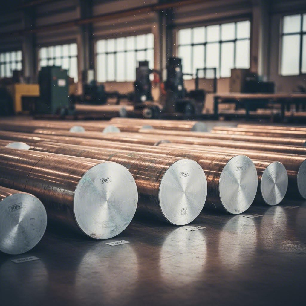
You've dialed in your press parameters, your die is in good condition, and your operators know what they're doing. So why does switching from 6063 to 6061 suddenly produce surface cracks that weren't there before? The answer lies in alloy chemistry. Each aluminum alloy family responds differently to the same process variables, and understanding these differences is the key to anticipating defects before they appear.
This is the gap most troubleshooting guides leave wide open. They'll tell you that surface cracking comes from excessive speed or temperature, but they won't tell you that 7075 needs extrusion speeds of 5-10 m/min while 6061 can handle 20-30 m/min without cracking. That kind of alloy-specific knowledge separates reactive troubleshooting from proactive defect prevention.
Aluminum alloys aren't interchangeable when it comes to extrusion behavior. The alloying elements — magnesium, silicon, zinc, copper — each influence how the metal flows, how it responds to temperature, and which defects it's most prone to. The table below maps the four most common extrusion alloys to their key characteristics, susceptible defects, and the process variables you need to watch.
| Alloy | Key Characteristics | Most Susceptible Defects | Process Variables to Watch |
|---|---|---|---|
| 6063 | Excellent extrudability, good surface finish, moderate strength. Contains Mg and Si forming Mg₂Si precipitates that lubricate flow. | Surface defects at high speeds (die lines, pick-up), orange peel from coarse grain structure | Extrusion speed (reduce at first sign of surface defects), billet homogenization quality, stretching force during straightening |
| 6061 | Higher strength than 6063, good weldability, moderate extrudability. Requires tighter temperature control. | Surface cracking if billet temperature is off, quench distortion in complex profiles | Billet temperature (450-480°C optimal), extrusion speed (20-30 m/min typical), quench uniformity |
| 6082 | High strength 6xxx alloy, good corrosion resistance. More sensitive to thermal processing than 6061. | Coarse grain recrystallization, surface cracking at elevated temperatures, orange peel | Extrusion temperature (avoid overheating), homogenization cycle, cooling rate after extrusion |
| 7075 | Extremely high strength, difficult to extrude, quench-sensitive. Contains Zn and Cu for precipitation hardening. | Surface cracking, stress corrosion cracking from uneven cooling, quench distortion | Extrusion speed (5-10 m/min maximum), billet temperature (480-520°C), quench rate and uniformity |
Notice the pattern? As alloy strength increases, extrudability decreases and defect sensitivity increases. The 6063 alloy that dominates architectural applications is forgiving — you can push it faster and recover from minor temperature variations. The 7075 alloy used in aerospace applications demands precision at every step.
The Mg₂Si precipitate phase in 6xxx alloys acts as a natural lubricant during extrusion, improving metal flow and reducing die wear. This is why 6063 produces such excellent surface finishes with minimal effort. But that same characteristic makes it sensitive to speed-related surface defects. Push the extrusion rate too high, and the lubrication effect breaks down, leading to pick-up and die lines.
For 7xxx alloys, the challenge is different. The zinc and copper additions that provide exceptional strength also increase deformation resistance. You need higher billet temperatures to achieve adequate plasticity, but those higher temperatures narrow the margin between successful extrusion and surface cracking. There's simply less room for error.
Here's a defect category that most extrusion industry news and technical guides completely overlook: quench-related defects. For heat-treatable alloys like 6061, 6082, and especially 7075, what happens during cooling can be just as important as what happens during extrusion.
The fundamental objective of quenching is to preserve the solid solution formed at elevated temperature by rapidly cooling to room temperature. When quenching rates aren't fast enough, solute precipitates on grain boundaries instead of remaining in solution for subsequent aging. This reduces tensile strength, yield strength, ductility, and fracture toughness. For most aluminum alloys, the critical temperature range is 400°C to 300°C — quenching must occur rapidly through this range to prevent unwanted precipitation.
But here's the tradeoff: faster quenching achieves better properties but increases distortion and residual stresses. The amount of warpage during quenching tends to increase with cooling rate. Aluminum has a large coefficient of thermal expansion, which means significant growth during solution heat treatment and contraction during quenching. If the part is constrained or cooling is uneven, stresses can exceed the yield strength at temperature, causing permanent distortion.
Quench sensitivity varies dramatically between alloys:
Distortion during quenching is probably responsible for most of the non-value-added straightening work in aluminum heat treating. An extreme example: aerospace wing spars over 3 meters long can warp dramatically from improper quenching and racking technique. The fix isn't always faster quenching — sometimes it's slower, more uniform cooling combined with proper part support.
Several factors influence quench distortion beyond alloy selection:
When you're troubleshooting distortion in heat-treatable alloys, don't assume the problem originated at the press. Check your quench parameters, part support, and cooling uniformity first. The defect you're seeing on the finished profile might have nothing to do with extrusion and everything to do with what happened in the quench tank.
Understanding alloy-specific behavior gives you a predictive edge, but some defect categories remain overlooked regardless of alloy. Weld seam integrity in hollow profiles and tail-end defects at the end of each billet cycle are structurally critical issues that deserve their own focused analysis.
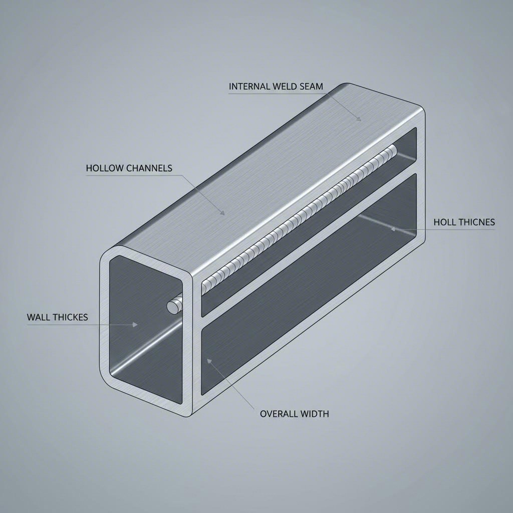
When you buy extruded aluminum hollow profiles, you're purchasing parts that contain hidden joints. Every aluminum extrusion hollow profile made through a porthole die has weld seams running its entire length — and if those seams aren't properly formed, the profile can fail under load without warning. Yet most quality discussions skip right past this structurally critical defect category.
The same goes for tail-end defects. Every billet cycle ends with a pressure drop that changes the microstructure and surface quality of the final meters of extrusion. And then there's handling damage — scratches and dents introduced after the profile leaves the press that get blamed on the extrusion process itself. These three overlooked categories account for a significant portion of extruded aluminum profile defects that slip through standard inspection protocols.
Imagine metal flowing through a porthole die. The billet splits into multiple streams as it passes through the ports, then those streams must rejoin in the welding chamber before exiting through the bearing. This rejoining happens through solid-state welding — no filler metal, no fusion zone, just two aluminum surfaces bonding under extreme pressure and temperature.
The mechanism is straightforward in principle: when clean aluminum surfaces contact each other under sufficient pressure at elevated temperature, atomic diffusion creates a metallurgical bond. But in practice, achieving complete bonding requires precise control of multiple variables. The aluminum extrusion weld seam forms where metal streams meet, and any weakness along this line compromises the entire profile's structural integrity.
What causes incomplete weld seam bonding? The root causes fall into three categories:
How do you test weld seam integrity? Visual inspection won't catch incomplete bonding — the seam looks fine on the surface. Instead, use these methods:
Remedies for weld seam defects focus on the three root causes:
Every extrusion cycle has a beginning and an end. At the end, something changes. As the ram approaches the bottom of its stroke, pressure drops and the billet skin — that contaminated outer layer — starts flowing into the die. The result is tail-end defects: sections of extrusion with different microstructure, surface quality, and mechanical properties than the rest of the profile.
The flow behavior of billet skin during extrusion follows two distinct paths: inward flow along the rear end of the billet, and forward flow along the dead zone boundary. In most conventional extrusion, inward flow dominates — the contaminated skin gets drawn into the center of the billet and eventually enters the die as the cycle ends. This creates back-end defects that degrade profile quality.
For miniature complex hollow profiles with ultra-large extrusion ratios, the problem intensifies. As profile size decreases, the proportion of back-end defects relative to total profile length increases significantly. A defect that represents 2% of a large profile might represent 10% or more of a miniature profile.
The discard length decision directly affects this tradeoff. Discard is the portion of the billet that remains in the container after extrusion — it gets cut off and recycled rather than becoming part of the finished profile. Longer discards mean less contaminated material enters the die, but they also mean lower yield and higher material cost per meter of usable profile.
Several factors influence optimal discard length:
Interestingly, research shows that ram speed and bearing length have only small effects on back-end defect length. Container temperature also barely affects billet skin flow behavior. This means your primary levers for tail-end defect control are friction management and die design, not press parameters.
Not every scratch on a finished profile came from the press. Post-extrusion handling — stretching, sawing, aging, and transport — introduces its own category of surface damage that often gets misattributed to the extrusion process itself.
Handling scratches occur due to improper handling, contact with sharp objects, or contamination during downstream operations. They differ from press-induced defects in several ways:
Other post-extrusion defects include:
The key to distinguishing handling damage from press-stage defects is pattern recognition. Press defects are systematic — they repeat consistently because they originate from a fixed condition in the die or process. Handling defects are random — they depend on how each individual piece was touched, moved, and stored.
When you're evaluating incoming material or troubleshooting quality issues, start by asking: is this defect consistent across multiple pieces, or does it vary randomly? Consistent defects point upstream to the press or die. Random defects point downstream to handling and logistics.
With these overlooked defect categories now covered, you have a complete picture of where quality problems originate. The next step is putting this knowledge into action with a systematic diagnostic framework that traces any visible defect back to its root process variable.
You've got a defect in front of you. Maybe it's a surface crack on a 6061 profile, or dimensional variation that's causing assembly failures downstream. The question isn't just what went wrong — it's where in the process it went wrong, and which specific variable you need to adjust first. This is where aluminum extrusion troubleshooting gets practical.
Most troubleshooting guides stop at describing defects. They'll tell you what surface cracking looks like, but they won't help you trace it back to the specific aluminum extrusion process variables that caused it. The diagnostic framework below fills that gap, giving you a systematic approach to extrusion defect diagnosis that works whether you're standing at the press or reviewing supplier quality reports.
When a defect appears, resist the urge to start adjusting parameters randomly. Instead, work through these four steps in sequence. Each step narrows the field of possible causes until you arrive at the specific variable that needs correction.
This four-step approach transforms reactive firefighting into systematic problem-solving. Instead of guessing which knob to turn, you're following a logical path from symptom to cause to remedy.
The table below is your quick-reference tool for aluminum extrusion root cause analysis. When you identify a defect, find it in the left column, then work across to identify the most likely origin stage and the first two variables to investigate. This mapping is based on the metallurgical and mechanical mechanisms discussed in earlier sections.
| Visible Defect Symptom | Most Likely Origin Stage | First Variable to Check | Second Variable to Check |
|---|---|---|---|
| Die lines (longitudinal grooves) | Die bearing zone | Bearing surface condition | Die temperature |
| Pick-up (comet-tail particles) | Die bearing zone | Die cleanliness and lubrication | Extrusion speed |
| Surface cracking (transverse cracks) | Press stage | Ram speed | Billet temperature |
| Blistering (raised bubbles) | Billet preparation / Press stage | Billet porosity and moisture | Filling speed during extrusion start |
| Orange peel (dimpled texture) | Press stage / Heat treatment | Billet homogenization quality | Stretching force |
| Twist or bow | Die design | Bearing length uniformity | Cooling uniformity on runout table |
| Wall thickness variation | Die design / Press stage | Bearing length distribution | Ram speed consistency |
| Weld seam weakness (hollow profiles) | Die (porthole configuration) | Welding chamber pressure | Billet and die temperature |
| Quench distortion | Runout table / Cooling | Quench rate uniformity | Part support and racking |
| Tail-end defects (end-of-billet) | Press stage (cycle end) | Discard length setting | Dummy block friction |
| Random scratches and dents | Post-extrusion handling | Handling procedures | Protective coverings and storage |
| Porosity (internal voids) | Billet preparation | Billet quality and degassing | Casting practices |
Notice how some defects share origin stages but require different first-check variables. Surface cracking and blistering both involve the press stage, but cracking points you toward speed and temperature while blistering points toward billet quality and filling dynamics. The mapping table helps you avoid wasting time on variables that aren't relevant to your specific defect.
Imagine you're seeing white line defects on anodized 6063 profiles — streaks that only become visible after surface treatment. Where do you start? Following the four-step framework:
This systematic approach works for any defect type. The key is resisting the temptation to skip steps. When you jump straight to adjusting parameters without first identifying the origin stage, you risk making changes that don't address the actual cause — or worse, introducing new problems while chasing the wrong variable.
Effective troubleshooting isn't about knowing every possible cause — it's about systematically eliminating causes until you find the one that matters.
With this diagnostic framework in hand, you can trace any visible defect back to its root process variable. But troubleshooting is only half the equation. For quality and procurement managers evaluating suppliers, the question shifts from fixing defects to preventing them in the first place — and that requires understanding what a defect-aware supplier's process controls actually look like.
You've learned how to diagnose defects and trace them to root causes. But what if you're not running the press yourself? For quality and procurement managers, the challenge shifts from troubleshooting to prevention — specifically, evaluating whether a custom aluminum extrusion supplier has the process controls in place to deliver consistent, defect-free output before problems show up in your incoming inspection.
Here's the reality: many procurement projects start with similar quotations but end with vastly different results. Some suppliers fail at dimensional consistency. Others deliver poor surface finishes or struggle with on-time delivery. Without a structured evaluation framework, these issues remain hidden until full-scale production begins — leading to rejected parts, assembly delays, and costs that far exceed any savings from a lower unit price.
Every supplier evaluation needs an objective benchmark. For aluminum extrusions, that benchmark is the Aluminum Association (AA) dimensional tolerance standards, which define acceptable limits for wall thickness, straightness, twist, and cross-sectional dimensions. These aluminum extrusion tolerance standards provide the common language between buyer and supplier — when you specify AA Standard tolerances, both parties know exactly what constitutes an out-of-tolerance condition.
Industry standards like ASTM-B-221 and AMS-QQ-A-200/8 guide process consistency and traceability for precision applications. A supplier operating under AS9100 registration demonstrates a proactive approach to identifying defects and minimizing risks — particularly important for aerospace, defense, and medical applications where a fraction of a millimeter can determine performance and safety.
When evaluating a supplier's aluminum extrusion inspection process, ask these questions:
Suppliers that can answer these questions with specific documentation — not vague assurances — demonstrate the aluminum extrusion supplier quality systems that prevent defects rather than just detecting them.
Process capability matters more than factory size. A supplier with 50 presses but poor process discipline will produce more defects than a smaller operation with rigorous controls. When auditing potential suppliers, look for evidence of systematic quality management across these key areas:
What does this look like in practice? Consider a supplier like Shengxin Aluminium, which operates 35 extrusion presses ranging from 600T to 5500T alongside CNC machining centers for precise cutting, drilling, and bending. Their surface treatment range — Anodizing, Powder Coating, PVDF, and Micro-arc Oxidation — indicates the infrastructure needed to control quality from die development through final finishing. This kind of vertical integration reduces handoffs between facilities and keeps process variables under one roof.
During on-site audits, watch for subtle indicators of process discipline: calibration certificates for measuring tools, consistent labeling between production and packaging areas, and operators who can clearly describe QC procedures. These details reveal whether quality systems exist on paper or in daily practice.
Defect rates connect directly to operational cost. Every rejected part represents material waste, rework labor, and potential delivery delays. A supplier with documented process controls and standards-based inspection protocols may quote slightly higher than competitors — but the total cost of quality, including scrap, returns, and production disruptions, often makes them the more economical choice.
The most common defects include die lines (longitudinal grooves from bearing surface irregularities), surface cracking from excessive speed or temperature, blistering caused by trapped gas, pick-up particles from die contamination, dimensional variations from uneven metal flow, and weld seam weakness in hollow profiles. Each defect originates at specific process stages - billet preparation, press operations, die conditions, cooling, or post-extrusion handling - and requires targeted remedies based on root cause analysis.
Surface cracking prevention requires controlling the interaction between extrusion speed, billet temperature, and profile geometry. Reduce ram speed to lower surface temperature, optimize billet temperature for improved plasticity (450-480°C for 6061, 480-520°C for 7075), and increase die corner radii to minimize stress concentration. Different alloys have varying speed tolerances - 6061 handles 20-30 m/min while 7075 requires only 5-10 m/min to avoid cracking.
Weld seam defects in hollow profiles result from incomplete solid-state bonding in porthole dies. Three primary causes exist: insufficient welding chamber pressure preventing oxide film breakthrough, temperatures too low for proper atomic diffusion, and contaminated billet surfaces introducing oxides or intermetallic compounds into the weld zone. Testing methods include flattening tests, burst pressure testing, and metallographic examination to verify seam integrity.
Alloy chemistry significantly impacts defect susceptibility. 6063 offers excellent extrudability but is sensitive to surface defects at high speeds. 6061 requires tighter temperature control to prevent cracking. 6082 is prone to coarse grain recrystallization. 7075 is highly quench-sensitive and demands precise speed control (5-10 m/min maximum). As alloy strength increases, extrudability decreases and the margin for process error narrows considerably.
Evaluate suppliers against Aluminum Association (AA) dimensional tolerance standards and look for documented process controls including: die maintenance practices with life tracking, billet traceability with chemical composition verification, automated temperature and pressure monitoring, in-house surface treatment capabilities, and comprehensive inspection protocols. Suppliers like Shengxin Aluminium demonstrate quality infrastructure through vertically integrated operations with 35 extrusion presses, CNC machining centers, and multiple surface treatment options from anodizing to PVDF coating.


 Інтернет-сервіс
 0086 136 3563 2360
 sales@sxalu.com
 +86 136 3563 2360
 Українська
 English
 français
 Deutsch
 русский
 español
 português
 العربية
 ไทย
ไทย Việt
Việt